Sheet metal bending looks straightforward: apply force along a straight line and form a flat sheet into the required angle. However, producing parts that meet dimensional tolerances consistently requires more than selecting a bending angle. Material properties, bend radius, tooling geometry, bend allowance, springback, and part design all influence the final result.
For manufacturers, mistakes in these areas can lead to incorrect flat patterns, cracked edges, distorted holes, inconsistent flange dimensions, and repeated adjustments during production. These problems become even more expensive when manufacturing large batches or working with different materials and thicknesses.
A reliable sheet metal bending process starts with understanding how the material behaves during deformation, calculating the correct flat pattern, and designing parts around practical manufacturing limitations. This guide explains the key engineering principles, common calculations, and design considerations that help manufacturers improve bending accuracy, reduce material waste, and achieve more consistent production results.
The Three Numbers That Decide Every Bend
Inside radius (R) is the radius of the concave surface, the side the punch presses into. It is not the outside radius, which is R plus the thickness.
The K-factor locates the neutral axis inside the thickness as a fraction of it: K = t / T, where t is the distance from the inside surface to the neutral layer. At K = 0.5 the axis sits at mid-thickness; real bends put it closer to the inside face. That is why published press brake figures fall between about 0.3 and 0.5, and why the same source reports a different value for each material, forming method and radius-to-thickness ratio.
Bend allowance (BA) is the arc length of the neutral axis through the bend. The flat pattern follows:
- BA = (π/180) × A × (R + K × T)
- Outside setback: OSSB = tan(A/2) × (R + T)
- Bend deduction: BD = 2 × OSSB − BA
- Blank length = sum of outside dimensions − sum of BD
A is the bend angle in degrees, T the thickness. At 90° the tangent term is 1, so OSSB reduces to R + T — which is why the formula gets treated as arithmetic and the part that matters gets skipped.
Only R is something a designer can point at. K is a function of R, the material and the method; BA and BD are consequences. Get R wrong and the other two are wrong however carefully you picked K.
Start With the Radius, Not the K-Factor
Most guides argue about which K-factor to use. That argument starts one step too late.
In air bending the sheet touches the tool in three places: the punch tip and the two die shoulders. It never reaches the die flanks. Angle comes from ram depth, not die angle, and the radius that forms is the larger of the punch tip radius or the natural radius the opening allows — for a sharp punch, near 0.16 × V in the usual shop approximation, which is worth confirming on your own tooling.
That explains why a drawing marked R2 comes out R1.9 on one machine and R2.6 on another. A 2 mm sheet over a 12 mm opening lands near R1.9; the same sheet over 16 mm lands near R2.6. Neither shop is wrong; they are using different dies.
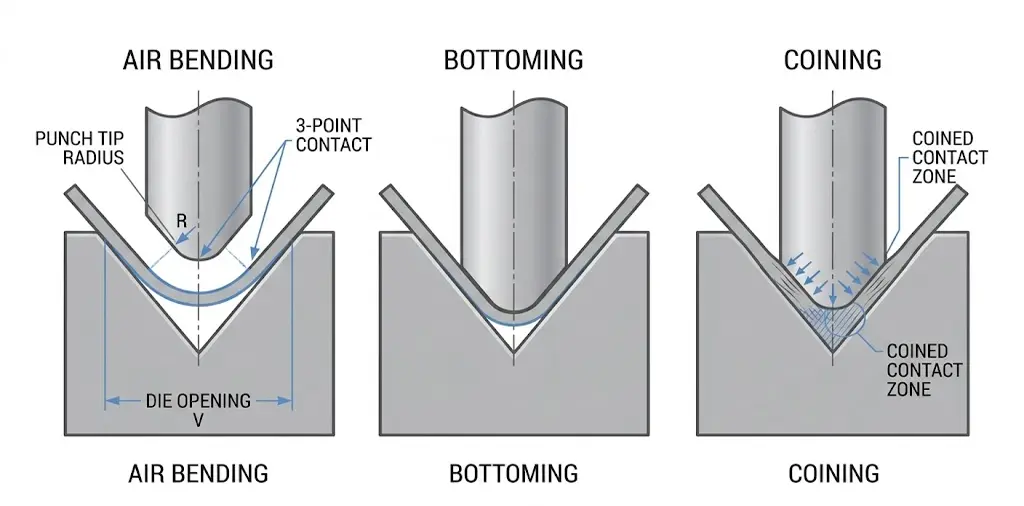
Two other methods behave differently at the design stage:
- Bottoming. The outside of the bend reaches the bottom of the V. Die geometry now controls the angle, the ram only sets force, and a K calibrated for air bending no longer applies.
- Coining. Material at the bend root is compressed until it fills punch and die. Springback nearly disappears; tonnage multiplies, typically several times the air-bending figure and often past what the tooling is rated for.
The design consequence is uncomfortable and useful. Specifying an exact inside radius forces the shop to find a die that produces it, which may mean a die it does not own. Specifying a maximum — “R2 max”, or any radius up to 2 mm — lets the shop use the die already on the machine, and the flat pattern follows from that die instead of fighting it. Radius tolerance costs money in proportion to how tight it is, and most parts do not need it tight.
The Same Drawing, Four Different Blanks
A job any shop could run this week: 2.0 mm 304 stainless, one 90° bend, two 40 mm outside flanges. The outside dimensions never change. Only the assumption behind the flat pattern does.
| Assumption behind the blank | Inside radius | K | Bend allowance | Bend deduction | Blank |
|---|---|---|---|---|---|
| 12 mm die (6t), sharp punch, common default K | 1.9 mm | 0.446 | 4.39 | 3.41 | 76.59 |
| Same die, K from a soft-material table | 1.9 mm | 0.330 | 4.02 | 3.78 | 76.22 |
| Same die, K from a wide-radius table | 1.9 mm | 0.500 | 4.56 | 3.25 | 76.76 |
| 16 mm die (8t), same default K | 2.6 mm | 0.446 | 5.49 | 3.72 | 76.29 |
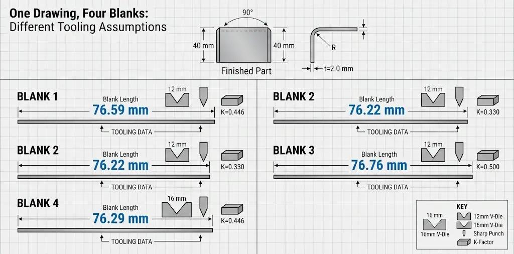
Four rows, one drawing, blanks spanning 0.53 mm from 76.22 to 76.76. Exactly one matches what the die on the machine will do. At ±0.2 mm — ordinary for a part this size, a 0.4 mm band — the spread is wider than the entire band, and whichever row is right, two of the other three fall outside it.
Watch the direction of the error, because it is counter-intuitive. A smaller K gives a shorter blank: the neutral axis moves toward the inside face, the radius it travels around shrinks, the arc shortens. Shops that “add a bit to be safe” usually move the wrong way.
Watch also which change did the damage. Sweeping K across its whole plausible range moved the blank 0.53 mm. Changing the die, and therefore the radius, moved it 0.30 mm before K was touched — and the die change is the one nobody writes down, because it happens on the floor after the drawing was approved.
So the flat pattern is a process document, not a design document. The designer owns the finished geometry. The shop owns the number that turns it into a blank, and that number belongs to one combination of material, die and machine.
Materials: Formability Is Not Strength
Designers reach for yield strength because it decides whether the part survives service. At the press brake it is half the story; the other half is how far the outer fibre stretches before it tears. A high-strength sheet with low elongation cracks at a radius a much weaker, more ductile sheet takes without complaint.
| Material | At the bend | Radius start | Springback | Force vs mild steel | Typical use |
|---|---|---|---|---|---|
| Cold-rolled / mild (DC01, A36) | Predictable, forgiving | ≈ 1 × T | Low | 1.0 | Brackets, frames, general fabrication |
| Hot-dip galvanised | Base metal fine, coating is not | ≈ 1 × T | Low | ≈ 1.0 | HVAC ducting, electrical cabinets |
| 304 / 316 stainless | Work-hardens as it forms | ≈ 1.5–2 × T | Medium to high | ≈ 1.4–1.6 | Food and medical equipment, architectural parts |
| 5052-H32 aluminium | Ductile, soft surface | ≈ 1 × T | Medium | ≈ 0.5–0.6 | Enclosures, panels, transport components |
| 6061-T6 aluminium | Heat-treated, little reserve | Mill data sheet | High | ≈ 0.7–0.8 | Structural brackets, machined assemblies |
| HSLA / AHSS | Resists deformation, loads the tooling | Mill data sheet | High | ≈ 1.5–2.5+ | Automotive, load-bearing structures |
The force column is a ratio, not a lookup table: at the same thickness and opening, forming force scales roughly with tensile strength, so divide your material’s tensile strength by that of the mild steel the shop normally runs. Take both from mill certificates for the actual heat.
The high-strength end needs a warning beyond tonnage. Tooling suppliers describe a chain: advanced high-strength steels need more stress to deform, they load die, press and handling equipment harder, and where the grade is strong with low ductility they spring back, raising stress in the tooling until fatigue cracking and chipping arrive earlier than a mild-steel job would bring them. A part that is comfortable on a 100-tonne brake in mild steel can be a tooling problem in AHSS at the same calculated tonnage.
Two facts design reviews skip. Grain direction: a bend line across the rolling direction stretches the outer fibre along its more ductile axis; a line parallel to the grain concentrates strain along it, and that is where cracks open on hard-tempered aluminium and high-strength steel. A part nested without regard to grain leaves the shop no choice. Surface: galvanised, pre-painted and polished sheets fail at the coating before the base metal does, so coating type and adhesion can set a stricter radius limit than the steel underneath — and on cosmetic faces the die shoulder’s mark is its own defect, covered in preventing die marks and scratches. The cheapest fix is a radius changed at design time, not a polishing step after the fact.
What the Die Opening Changes
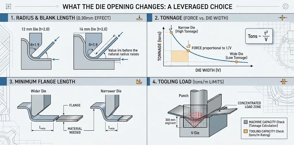
The die opening is the most leveraged choice in the process because it moves four things at once. Six to eight times thickness is the conventional start; how the V-die opening is chosen covers when to leave it.
- Radius. A wider V raises the natural radius, which changes K, which changes the blank — the 0.30 mm above.
- Tonnage. Force falls roughly in proportion to a wider opening and rises sharply with a narrower one. Thickness enters squared, so a small gauge change on a narrow die is not a small tonnage change.
- Minimum flange. A wider die needs more material on the shoulder before a bend forms at all. Short flanges are a die problem before they are an operator problem; the calculation is in minimum flange length.
- Tooling load. Tonnage per metre has a ceiling that belongs to the punch and die, not the machine. A 100-tonne rating says nothing about whether a 300 mm segment of tooling can take what you put into it — a separate check, tons per metre limits.
Both checks belong before the job reaches the machine: machine capacity through the tonnage calculation, tooling capacity through its own rating, especially when the bend is short and concentrated rather than spread across the bed.
Design Rules That Survive the Press
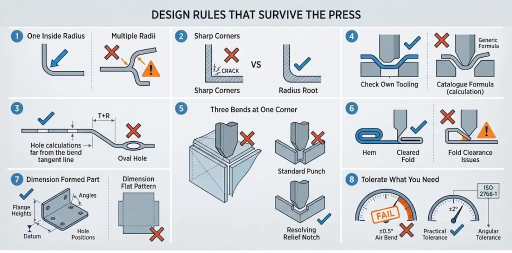
1. One inside radius per part. Every distinct radius is a potential tool change. A part with three radii costs more than a part with one and looks no different.
2. No sharp internal corners. A zero-radius corner puts all the strain on one line, the classic origin of a tear. Give inside corners a radius at least comparable to thickness, and radius the root of any relief notch — a square notch only moves the crack.
3. Keep holes and slots out of the deformed zone. 2.5 × T + R from the bend tangent is the usual floor, not a rule: the zone widens with radius and die opening, so a generous bend needs more clearance than a tight one, and a hole inside it comes out oval however the press is adjusted.
4. Check the flange against the tooling. Published formulas disagree because they answer different questions: 0.5V + 2T sizes the part across the die shoulders, 4T + R comes out of tooling catalogues. Neither substitutes for checking the punch and die you own.
5. Watch three bends meeting at one corner. Where three flanges converge, the punch has nowhere to go. Relief, a different bend order, or different tooling resolves it; the cases are worked through in bending deep boxes and cabinets without tooling interference.
6. Leave room for hems and for the bend order. A hem consumes material and needs clearance for the fold, and if it sits next to another bend, geometry fixes the order rather than preference. See hemming and flattening on a press brake.
7. Dimension the formed part, not the blank. Flange heights from a defined datum, angles, hole positions after forming. Specifying the flat pattern hands a process decision to the wrong party and guarantees an argument when the shop’s die produces a different K. Say which flange actually matters and to what — the failure modes are in wrong flange dimensions.
8. Tolerate only what you need. ISO 2768-1 applies to untoleranced dimensions; its scope explicitly covers parts formed from sheet metal, and the 1989 edition is being replaced by a revised ISO 2768. A general-tolerance class says nothing about what the process can hold, though, and a bend angle is better controlled by a stated angular tolerance. Demanding ±0.5° on an air bend asks for something the process does not deliver reliably across a batch.
Defects: Find the Cause Before Adjusting
| Symptom | Usual cause | First move |
|---|---|---|
| Cracking on the outside of the bend | Radius too small for the grade, grain parallel to the bend line | Increase radius or change grain orientation; check elongation |
| Flange dimension off by a constant | Wrong bend deduction in the table | Re-derive BD from a test bend, not a default K |
| Angle varies along a long part | Ram or bed deflection | Check alignment, then crowning |
| Angle drifts between batches | Material strength or thickness variation | Compare mill certificates, re-test the heat |
| Holes oval or displaced | Feature inside the deformed zone | Move the feature, punch after bending, or add relief |
| Flange will not form at all | Flange shorter than the die can support | Narrower die or different punch |
If several appear at once, stop adjusting the program. Tooling wear, machine deflection and setup are all candidates, and the program is the least likely of the four.
Springback: Design It In, Don't Chase It
Every bend springs back when the load releases: the outside recovers its stretch, the inside its compression, the included angle opens. Strength and modulus, radius-to-thickness ratio and forming method set how far — stronger material, larger radius and thinner section all make it worse.
The design levers beat anything at the machine. A larger radius relative to thickness raises springback but lowers cracking risk, and the window where both are acceptable is wider than most drawings assume. Annealed temper springs back less than hard temper of the same alloy, at some cost in strength. And the angle callout should match what the process can hold rather than what the assembly would like.
Compensation — overbending, bottoming, closed-loop correction — trades tonnage, tooling life and cycle time against each other, and is covered in springback in sheet metal bending; bending angle measurement closes the loop during the cycle instead of at inspection. The narrower point: choose material and radius so the springback you must compensate is predictable, rather than discovering an unpredictable one after the tooling is cut.
Who Owns the Flat Pattern
Three parties touch the flat pattern and each owns a different part of it.
| Party | Owns | Does not own |
|---|---|---|
| Design | Finished geometry, datums, which dimensions matter, maximum acceptable radius | K-factor, die choice, bend sequence |
| Process / programming | Die and punch selection, bend order, the K or BD in the CAM bend table | Functional tolerances on the drawing |
| Shop floor | First-off verification, the measured correction stored for the next run | Redesigning the part to suit the tooling |
The handover that works is short. Take four or five strips from the same sheet the job will be cut from, bend them at production settings — same die, same punch, same ram depth, same direction to grain — and measure the formed outside dimensions and the flat length. Back out the bend deduction that reproduces the flat, or the K behind it, and write it into the CAM table for that material and tooling.
Then record it, because the value is only valid for the conditions it was measured under.
| Field | Why |
|---|---|
| Grade, temper, heat number | A different heat changes strength, and therefore springback |
| Measured thickness | Nominal is a promise; the micrometer is a fact |
| Punch tip radius and die V opening | Set the natural radius, the tonnage and the minimum flange |
| Bend line vs grain direction | Parallel-to-grain bends behave differently |
| Target angle, released angle, measured flange, resulting BD | This is the correction, and the number in the table |
| Date and approver | So the next person knows whether to trust it |
Four events invalidate the record and require a new test: a change of material supplier or heat, a change of die or punch, a change of machine, and a change of forming method — air bending to bottoming is a different process with a different K, not an adjustment. A shop storing one “stainless” K-factor for all stainless is wrong on most of its jobs and right by accident on a few.
Programming order follows. The blank has to be known before the sheet is cut, because cutting first leaves scrap as the only correction. Running the bend program first, even roughly, fixes the blank size, exposes collision and tool-access problems, and turns the first article into a confirmation instead of an experiment. Where the shop programs offline, the bend table is the file that carries this between jobs; controller-side support for importing and maintaining it sits under CNC software and control support.
Matching the Machine to the Part
Tonnage and length eliminate machines that cannot do the job. What separates the right machine from an adequate one is how well it holds the radius, the angle and the setup time your part mix needs. Four questions sort most enquiries:
- What is the longest bend, and how much tonnage does it take?
- How tight is the angle, and must it hold along the full length? That needs deflection compensation, not a stiffer frame.
- How many radii and tools does a typical job need? Tool changes move the economics more than approach speed.
- One product for years, or five of this and two of that? Job shops and product manufacturers should not buy the same machine.
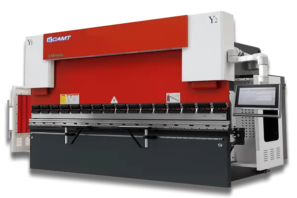
Within the press brake range: short parts and frequent changeovers suit the Smart 3–4 axis synchronous machine or the plainer Economy torsion bar, where the money goes into capacity rather than axes. Repeatable general fabrication points to the Genius 4–6 axis; multi-axis backgauging and tight angle control to the Apex 6–8 axis, where crowning and backgauge selection do as much for accuracy as the frame. Thin-gauge, high-cycle, clean-environment work suits servo-electric machines, which remove the hydraulic circuit. Parts longer than one bed need a tandem; thick plate at high tonnage belongs on a heavy-duty frame, not at the top of a standard model’s rating.
The trap is buying capacity you never use and finding the constraint elsewhere — too few backgauge axes for the part family, or a tooling system that cannot mount the punches the work needs. A control that simulates the bend sequence catches both before steel is cut, which is the real difference between CNC control systems. The machine is the cheapest part of a bending decision to change before the order and the most expensive afterwards.
Before You Release the Drawing
| Check | What to confirm |
|---|---|
| Material | Grade, thickness and its tolerance, temper, rolling direction |
| Geometry | One inside radius or "R max", angles, minimum flange, bend order |
| Flat pattern | Which K or BD, one dimensioning convention, developed length |
| Features | Hole and slot clearance, reliefs and their root radius, edge distances |
| Process | Punch and die compatibility, tonnage per metre, bed length, open height, crowning |
| First article | Sample bends measured, parameters recorded for repeat runs |
A documented setup costs nothing and cuts future setup time more than any machine upgrade at the same price.
Start anywhere in this series
Material-specific and calculation guides pick up where this one leaves off.
Frequently Asked Questions
What is the difference between bend allowance and bend deduction?
BA is the arc length of the neutral axis inside the bend — the material the bend consumes. BD is what you subtract from the sum of outside dimensions to get the blank. They describe the same geometry from opposite directions, and CAD gives the same flat length either way; mixing the two conventions in one bend table produces flanges wrong by exactly one bend deduction.
Which K-factor should I use for stainless steel?
None of the published ones until you have tested your own. Tables disagree because K depends on material, forming method and radius-to-thickness ratio, not on the alloy name. For 304 in air bending, 0.4–0.5 is a reasonable first estimate; production should run on the value measured from test strips on your die. A K that was right on a 6t die is not automatically right on an 8t die.
Can 6061-T6 be bent without cracking?
Sometimes, and it depends on radius, temper and grain direction rather than on the alloy. T6 has little reserve ductility and its minimum radius is several times the thickness; the figure is in the mill’s data sheet for the specific product form. Where formability matters more than strength, 5052-H32 is the usual substitute. Where T6 is required structurally, specify a generous radius, control grain in the nest, prove it on a test piece.
How close can a hole be to a bend line?
Start at 2.5 × T + R from the bend tangent, measured from the nearest hole edge rather than its centre. That is a floor: the deformed zone widens with radius and die opening, so a position safe on a tight die can distort on a wide one. If the design needs it closer, punch after bending, add a relief, or move the bend line — all three cost more than moving the hole.
Do I need a different die for every thickness?
No, but the opening has to stay in a workable relationship with it. Six to eight times thickness is the usual band, and leaving it changes radius, tonnage and minimum flange together. A shop runs a small set of openings and accepts that radius varies between them — another argument for a maximum radius rather than an exact one.
Conclusion
Three numbers decide a bend: inside radius, K-factor, and the bend allowance that follows. Only the first is a design decision, and on an air bend even that is negotiated with the die the shop happens to own.
So the flat pattern deserves the attention the drawing gets. A blank built on a default K, cut before anyone checked the die, is a commitment to a number nobody measured. The shops that bend difficult material well are not the ones with the best tables; they test-bend, record what they measured, and re-test when material, die or machine changes.
If you are working through a specific part, our engineers review radius, die opening and tonnage against the material specification as part of the quotation. Send us the drawing and the conversation gets more useful once we can see the part.