A part can meet its bend-angle and dimensional requirements yet still fail inspection because of scratches, pressure lines, or visible die marks. These defects are particularly costly when bending brushed stainless steel, polished aluminum, pre-painted sheets, or other materials with exposed cosmetic surfaces. In most cases, the problem is related to friction, excessive or concentrated contact pressure, contaminated tooling, or unsuitable punch and die geometry. Preventing surface damage requires more than placing protective film over the lower die. It involves controlling the entire bending process, from material handling and tooling selection to machine setup and production inspection.
The practices that make the biggest difference:
- Identify the mark before adjusting anything — its position, direction, and pattern point to the cause.
- Keep die shoulders smooth, generously radiused, and free of material pick-up.
- Match the tooling and protection method to the material: films, urethane drapes, soft inserts, or roller-type dies.
- Control bending force and prefer air bending for cosmetic work where tolerances permit.
- Inspect tooling and handle parts deliberately — a large share of “bending scratches” happen outside the bending stroke.
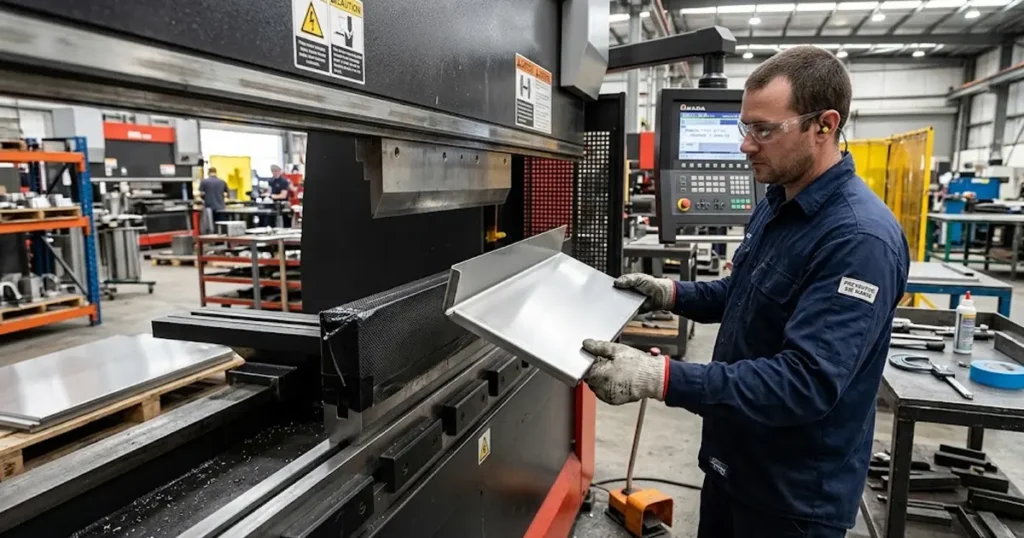
Why Do Die Marks and Scratches Occur During Press Brake Bending?
During conventional V-die air bending, the sheet metal rests on two shoulders of the lower die while the upper punch pushes the material downward. As the bend develops, the sheet slides across the die shoulders under increasing contact pressure.
This combination of pressure and relative movement creates friction between the workpiece and tooling. If the contact surfaces are rough, contaminated, damaged, or poorly matched to the material, visible marks can develop along the bend area.
There are three main types of surface damage to distinguish:
- Sliding scratches: Long scratches or abrasion lines caused by the sheet moving across the lower die shoulders or other contact surfaces.
- Pressure marks (die impressions): Visible lines or indentations caused by concentrated contact pressure between the workpiece and tooling.
- Tooling-related scratches: Localized scratches caused by sharp edges, damaged tool surfaces, metal particles, or uneven joints between segmented tooling.
Understanding the defect pattern is the first step toward finding the actual cause.
1. Friction Between the Sheet and Lower Die Shoulders

Sliding friction is one of the most common causes of scratches during V-bending.
As the punch moves downward, the sheet is drawn into the V-opening. Its contact points move along the two lower die shoulders, creating relative movement between the sheet and tooling.
The problem becomes more noticeable when processing brushed stainless steel, mirror-finished aluminum, and other materials with highly visible surface finishes.
Several conditions can increase scratching:
- Rough or worn die shoulder surfaces.
- Sharp or damaged die shoulder radii.
- Excessive friction caused by unsuitable contact conditions.
- Incorrect die opening for the material and thickness.
- Repeated sliding across an unprotected steel surface.
The shoulder radius deserves particular attention. A widely used guideline from press brake tooling specialists is to keep the die shoulder radius at roughly two to three times the material thickness; below that, the shoulder tends to scrape the surface instead of letting the material slide across it, and the difference shows up immediately on stainless and aluminum. Dies with very small shoulder radii still have their place — but they are best reserved for parts where the surface finish does not matter.
For brushed stainless steel, even a relatively shallow scratch can interrupt the original grain pattern and remain visible after bending.
2. Metal Chips, Dust, and Contaminated Tooling
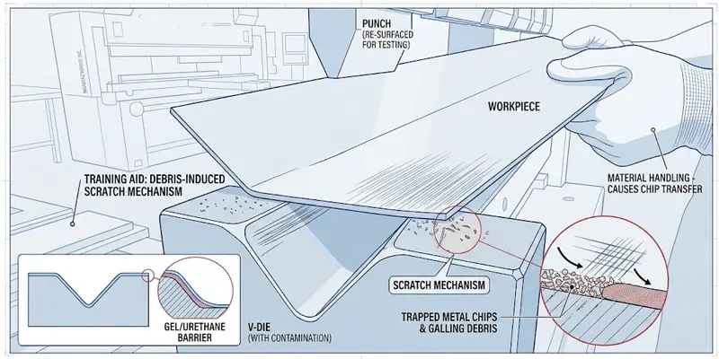
Sometimes, a die that appears to be in good condition still produces scratches.
The reason may be a small metal chip, burr, or piece of hardened debris trapped between the workpiece and tooling.
Under bending pressure, even a tiny particle can act like an abrasive point. As the sheet moves, it can produce a deep scratch or a series of repeated marks.
Common contamination sources include:
- Burrs and metal chips left after laser cutting or shearing.
- Grinding dust and welding debris.
- Residual particles from previous bending operations.
- Rust, scale, or damaged surface coatings on tooling.
- Dirt accumulated on the press brake bed and backgauge fingers.
This problem is especially difficult to identify when scratches appear randomly rather than consistently along the entire bend line.
A closely related mechanism deserves its own attention: galling. As the sheet slides across the die shoulder, small particles of the sheet surface — or dross from cut edges — can transfer onto the tooling and build up there. Aluminum is notorious for leaving residue on dies, and galvanized coatings transfer as well. Caught early, this pick-up simply wipes off. Left in place, the fragments build up and work-harden, and the shoulder starts scoring every part that follows.
What makes galling deceptive is that the die looks damaged. Run a fingernail along the shoulder and you feel a divot — but a damaged tool and a tool with galling start out looking nearly the same. If the “divot” has a raised ridge beside it, you are more likely feeling material build-up than a nick in the die. Cleaning galling early, while it still wipes off, is one of the highest-value habits in cosmetic bending.
3. Incorrect Punch and Die Selection
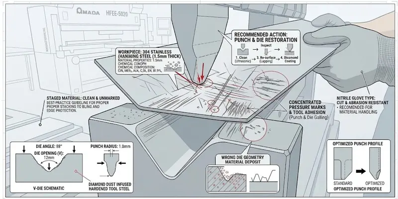
Tooling geometry directly affects how pressure and friction are distributed during bending.
A lower die with an unsuitable V-opening or a small shoulder radius can create concentrated contact pressure. Likewise, a damaged or excessively sharp punch tip can leave visible impressions on the inside surface of the bend.
The risk increases when operators select tooling based only on sheet thickness without considering material properties, bend radius, surface finish, and part geometry.
For example, using conventional hardened-steel dies for highly polished or pre-painted sheets may produce unacceptable contact marks even when the bending angle is correct.
Tooling selection should therefore consider both forming requirements and cosmetic quality requirements.
4. Excessive Contact Pressure During Bending

Higher bending force does not automatically mean better bending quality.
When the process uses unnecessary force, the sheet experiences greater contact pressure against the punch and die surfaces. This can make existing tooling marks more pronounced, particularly on soft aluminum, thin stainless steel, and pre-finished materials.
This issue is particularly relevant when bottoming or coining is used.
Unlike air bending, bottoming forces the material further against the die surfaces, while coining applies very high localized pressure to reproduce the tool profile.
If the application requires a clean cosmetic surface, air bending is often worth evaluating before selecting a more force-intensive forming method.
However, the correct process depends on the required angle tolerance, bend geometry, material behavior, and production specifications.
5. Workpiece Movement and Improper Material Handling
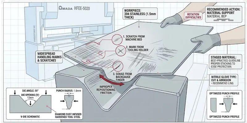
Not every scratch originates at the bending line.
Large sheets can drag across the machine bed, tooling holders, backgauge fingers, or support surfaces during positioning and repositioning.
This frequently happens when operators manually rotate heavy or oversized workpieces without sufficient support.
Long panels are particularly vulnerable because their weight can create uneven contact and additional friction during handling.
In these situations, changing the lower die alone will not solve the problem. The entire workpiece-support and handling process needs to be evaluated.
How to Prevent Die Marks and Scratches on Bent Parts
Once the source of surface damage has been identified, the next step is to select a suitable preventive measure.
There is no universal solution for every material or production environment. A method that works well for brushed stainless steel may not be suitable for thin coated aluminum or complex formed panels.
1. Use Protective Film or Non-Marking Die Solutions
For materials requiring a high-quality surface finish, placing a suitable protective layer between the sheet and lower die is one of the most practical ways to reduce direct metal-to-metal contact.
Common options include:
Polyurethane protective film
Urethane film is positioned over the lower die shoulders to create a protective barrier between the sheet and hardened steel tooling.
It is useful for:
- Brushed or polished stainless steel.
- Decorative aluminum panels.
- Pre-painted sheet metal.
- Small-batch production requiring flexible tooling arrangements.
In practice, urethane drapes around 90A durometer — fairly hard, with minimal stretch — wear well and can be held to the die with magnets, which grip even on lightly oiled surfaces. Tooling makers typically supply them in thicknesses around 0.010 to 0.030 inch, and the drape thickness should be included when sizing the V opening. The drape should be laid in so it sags into the opening before bending; pulled tight across the die, it stretches and thins under load.
However, protective film is a consumable rather than a permanent solution. It can wear, tear, shift, or become contaminated during repeated bending cycles.
Operators should inspect it regularly and replace it whenever its protective performance deteriorates.
Polyurethane or nylon protective inserts
For repeated production, dedicated non-marking die inserts can provide a more stable contact surface.
Unlike temporary film, these inserts are designed to remain in the tooling arrangement over multiple production cycles.
They are particularly useful when a manufacturer regularly processes cosmetic parts and needs more consistent surface protection.
Roller-type or rotating lower dies
In conventional V-die bending, the sheet slides over stationary die shoulders.
Roller-type tooling changes this contact behavior by allowing the supporting contact elements to rotate as the sheet moves. This can significantly reduce sliding friction and associated surface marking.
The appropriate solution depends on the material, bending geometry, required surface finish, and production volume.
2. Select the Correct V-Die Opening and Shoulder Radius
The lower die opening is an important factor in both bending geometry and surface quality.
An unnecessarily narrow V-opening can increase forming force and contact pressure, making visible die marks more likely.
However, simply choosing the largest available V-opening is not a reliable solution. The opening also affects the inside bend radius, minimum flange dimensions, required tonnage, and final bending geometry.
A practical selection process should consider:
- Material type and tensile strength.
- Actual sheet thickness.
- Required inside bend radius.
- Minimum flange length.
- Required bending angle.
- Machine tonnage and tooling load limits.
Surface finish matters as much as geometry. Tooling makers who specialize in cosmetic work hold die contact surfaces to very fine finishes — one tooling manufacturer recommends polishing the die’s lead-in radii to 32 microinches or better, noting that an excellent finish smooths the material flow into the die and reduces marking and galling. A polished shoulder also releases pick-up more easily, so it stays cleaner through the run.
The shoulder radius also deserves attention.
A properly selected, smooth shoulder radius helps the sheet move across the die contact area with less concentrated pressure. Increasing the shoulder radius can reduce scratching, but it must remain compatible with the required bend geometry and material behavior.
If the radius is unsuitable, the workpiece may develop an incorrect inside radius or other forming defects.
For this reason, die opening and shoulder radius should be evaluated together rather than adjusted independently.
3. Keep Punches and Dies Clean and Properly Maintained
Tooling inspection should be part of the normal production routine, especially before processing high-value cosmetic materials.
Before starting a bending job:
- Clean the upper punch and lower die surfaces.
- Remove metal chips, dust, rust, and other foreign particles.
- Inspect die shoulders for dents, burrs, scratches, and uneven wear.
- Check punch tips and contact radii for damage.
- Inspect segmented tooling joints for gaps or height differences.
- Confirm that the tooling is correctly installed and aligned.
When bending aluminum or galvanized material on cosmetic parts, check and wipe the die shoulders at setup and periodically through the run. The goal is to clean pick-up while it still wipes off. Once the build-up work-hardens, removal requires aggressive scraping — and scraping or abrasive pads do not pair well with precision-ground tooling surfaces.
Pay particular attention to the joints between segmented dies.
A small height difference or gap between adjacent segments can create a localized pressure point, leaving a visible mark on the workpiece.
If the same scratch repeatedly appears at a particular position along the bend, inspect the corresponding tooling section first.
Routine maintenance is usually less expensive than repeatedly polishing, repainting, or replacing rejected parts.
4. Control Bending Force and Select the Appropriate Forming Method
Correct force control helps prevent unnecessary pressure on the workpiece.
Operators should calculate the required bending tonnage according to material thickness, tensile strength, bending length, and die opening.
They should also verify that the selected tooling and machine are operating within their rated load limits.
For cosmetic parts, consider the following practices:
- Use air bending where the required angle and dimensional tolerances permit.
- Avoid unnecessary bottoming or coining.
- Do not increase pressure simply to compensate for incorrect tooling geometry.
- Confirm that the punch radius and die opening match the intended bend.
- Validate the setup through trial bending before production.
The objective is not to use the lowest possible force regardless of the application. It is to apply the appropriate force to achieve the required bend without unnecessary surface damage.
5. Protect the Workpiece During Positioning and Handling
Surface protection must continue before and after the actual bending stroke.
Even if the tooling contact is well controlled, a sheet can still be scratched when it slides across the machine bed or contacts unprotected support surfaces.
For large or heavy panels, suitable sheet follower supports can help carry the workpiece during bending and reduce uncontrolled movement.
Operators should also:
- Use clean gloves when handling polished or coated materials.
- Avoid dragging sheets across the machine bed.
- Keep backgauge contact points clean and free of sharp burrs.
- Use appropriate lifting and handling equipment for large panels.
- Maintain protective film on the sheet when it is suitable for the forming operation.
- Check that factory-applied film has no wrinkles, trapped debris, or damaged areas.
For long workpieces, consider whether the support arrangement is adequate throughout the entire bending sequence.
CAMT’s press brake bending follower supports can be evaluated for applications where large sheets require additional support during positioning and bending.
6. Maintain Stable Tool Alignment and Machine Compensation
Surface marking is primarily a tooling-contact problem, but machine stability can also influence the consistency of the bending process.
For long workpieces, ram and worktable deflection under load can create variations in bending conditions along the machine length.
This may lead to different contact pressure and bend results between the center and the ends of the workpiece.
A suitable crowning system compensates for machine deflection by adjusting the relationship between the upper and lower tooling across the working length.
Although crowning does not directly remove scratches or replace non-marking dies, it helps maintain more consistent bending conditions, particularly when processing long or heavy parts.
CAMT’s press brake crowning system provides mechanical and motorized compensation options for applications requiring more consistent bending accuracy along the workpiece.
How to Choose the Right Surface Protection Method
The best solution depends on the material, surface finish, production volume, and acceptable tooling cost.
The following table provides a practical starting point.
| Workpiece or production condition | Common surface problem | Recommended approach |
|---|---|---|
| Brushed stainless steel | Scratches that interrupt the grain pattern | Protective urethane film, non-marking inserts, clean tooling |
| Mirror-finish stainless steel | Fine scratches and visible pressure lines | Dedicated protective tooling, careful handling, clean contact surfaces |
| Polished aluminum | Surface indentation and abrasion | Protective film or soft-contact die solutions |
| Pre-painted sheet metal | Coating scratches and pressure marks | Suitable protective layers, smooth tooling, controlled contact pressure |
| Anodized aluminum | Scratches and localized coating damage | Protective inserts or film, careful material handling |
| Repetitive cosmetic production | Recurring marks across batches | Dedicated non-marking tooling and standardized inspection |
| Long panels | Scratches during movement and uneven support | Protective tooling, suitable follower supports, stable machine compensation |
One important consideration: protective film and factory-applied sheet film are not interchangeable in every application. Their thickness, flexibility, adhesion, and compatibility with the forming process should be checked before production.
A Practical Troubleshooting Checklist for Existing Surface Defects
If scratches or die marks have already appeared in production, replacing the tooling immediately may not be necessary.
A systematic inspection can help identify the actual cause and avoid unnecessary equipment or tooling expenses.
Step 1: Identify the Location and Pattern of the Defect
Start by examining where the damage occurs.
- Two parallel lines along the bend: Inspect the lower die shoulders and their contact surfaces.
- A scratch extending in the sheet movement direction: Check for sliding friction, trapped particles, and damaged tooling.
- A localized dent or bright spot: Inspect for concentrated pressure, burrs, or foreign objects.
- A mark at a tooling segment joint: Check the height difference, gap, and alignment between segments.
- Scratches away from the bend line: Inspect the machine bed, backgauge, support equipment, and handling process.
- A continuous line on the inside bend surface: Inspect the punch tip and its radius.
One test helps date the damage before anything is disassembled: check whether the mark was deformed by the bend. A scratch that runs across the bend line and continues over the formed radius, stretched and distorted with the material, was already on the sheet before forming. A bright band parallel to the bend points to contact during forming. A sharp, undeformed scratch on a flat face away from the bend line was almost certainly created after bending — during part removal, staging, or handling.
These patterns are diagnostic clues rather than definitive proof. Confirm the suspected cause through controlled inspection and trial bending.
Step 2: Check the Material Before Adjusting the Machine
Compare the damaged workpiece with an unprocessed sheet from the same batch.
Look for:
- Existing scratches or surface contamination.
- Burrs around cut edges and openings.
- Damaged protective film.
- Variations in material thickness.
- Different surface finishes or grain directions.
This step helps determine whether the defect existed before bending or was introduced during processing.
Step 3: Inspect the Entire Tooling Setup
Check the punch and die for:
- Surface roughness and visible damage.
- Foreign particles and accumulated debris.
- Incorrect tooling combinations.
- Improper installation or alignment.
- Uneven contact between segmented tools.
If possible, test with a clean, verified tooling set to determine whether the defect follows the original tooling.
Step 4: Run a Controlled Trial
Change one variable at a time.
For example:
- Clean the existing tooling and run a test piece.
- If marking remains, try an appropriate protective film.
- Evaluate a different die opening or shoulder radius if the bend geometry permits.
- Compare air bending with the existing forming method where technically feasible.
- Inspect the result before changing additional machine parameters.
Record the material specification, thickness, tooling combination, die opening, bending method, and inspection result.
This makes it easier to establish a repeatable production setup instead of relying on operator guesswork.
Step 5: Establish a First-Piece and In-Process Inspection Standard
Once the surface defect has been corrected, the solution should be documented.
A practical inspection standard should include:
- Approved tooling identification.
- Material and surface-finish requirements.
- Protective film or insert specifications.
- Machine setup parameters.
- Acceptable surface condition and inspection lighting.
- Protective film replacement criteria.
- First-piece approval and periodic inspection frequency.
Without a documented standard, the same surface defects may return when operators change shifts, tooling is replaced, or a repeat order enters production.
How CAMT Press Brake Solutions Help Improve Bending Quality
Preventing die marks is not simply a matter of purchasing a more powerful press brake. The machine, tooling, compensation system, and material-handling arrangement must work together.
For manufacturers processing stainless steel panels, aluminum enclosures, architectural components, or other appearance-critical sheet metal parts, the equipment configuration should match the actual production requirements.
CAMT provides several solutions that can support this process.
CNC Press Brakes for Consistent Bending Operations
CAMT’s CNC press brake machines are designed for accurate, repeatable bending across different materials, thicknesses, and part geometries.
Multi-axis control and suitable machine configurations help manufacturers standardize bending operations and reduce setup variation.
For cosmetic applications, the machine should be configured with appropriate tooling and surface-protection measures rather than relying on machine accuracy alone.
Tooling Clamping and Positioning Solutions
Incorrectly installed or poorly aligned tooling can create uneven contact conditions and inconsistent bending results.
CAMT’s press brake tooling clamping systems provide manual, hydraulic, and pneumatic clamping options, with alignment and adjustment features designed for different tooling configurations.
Proper installation and alignment help maintain stable contact between the punch, die, and workpiece.
Crowning for Long and Heavy Workpieces
When bending long panels, machine deflection can affect the consistency of the bending process.
CAMT’s mechanical and motorized crowning systems compensate for ram and worktable deflection to improve angle consistency along the working length.
This is particularly relevant when the same cosmetic part must maintain consistent bending results from one end to the other.
Technical Support for Tooling and Process Optimization
When surface defects continue despite cleaning and basic setup adjustments, a more detailed engineering assessment may be necessary.
CAMT’s technical support services can help evaluate machine setup, tooling selection, and bending-related production issues.
For difficult applications, manufacturers can provide material specifications, component drawings, photos of the surface defects, and existing tooling information for technical evaluation.
This is one failure mode in a longer sequence. The press brake troubleshooting guide starts from the defect signature and narrows it to machine, tooling, material or method.
Frequently Asked Questions
What causes scratches on sheet metal after press brake bending?
Most scratches are caused by friction between the sheet and tooling, especially when the material slides over the lower die shoulders. Damaged tooling, metal chips, dust, unsuitable die geometry, and improper material handling can also produce scratches.
How can I prevent die marks when bending stainless steel?
Start with clean, smooth tooling and an appropriate V-die opening and shoulder radius. For brushed or polished stainless steel, consider urethane protective film, dedicated non-marking inserts, or specialized low-mark tooling. Always inspect the protective layer and conduct trial bends before batch production.
Does a larger V-die opening reduce surface marking?
A suitable larger V-opening can reduce contact pressure in some applications, but it also changes the inside bend radius, required tonnage, and flange requirements. The correct opening must be selected according to the material, thickness, and required bend geometry.
Can protective film completely eliminate die marks?
Not necessarily. Protective film can reduce direct metal-to-metal contact and friction, but it may tear, shift, wear, or trap particles. It also cannot correct damaged punches, poor tooling alignment, or scratches caused during material handling.
Is air bending better than bottoming for cosmetic sheet metal?
Air bending is often worth considering because it generally requires less force and avoids pressing the sheet fully against the V-die cavity. However, the best forming method depends on angle tolerances, material properties, geometry, and production requirements.
Why do scratches appear in random locations instead of along the entire bend?
Random scratches often indicate loose metal particles, contaminated tooling, damaged protective film, or inconsistent material handling. Inspect the sheet, punch, die, backgauge, and support surfaces before making major machine adjustments.
Final Thoughts
Die marks and scratches are not inevitable consequences of press brake bending. Although contact pressure and friction are inherent in the forming process, their effects can be controlled through appropriate tooling geometry, protective materials, clean working surfaces, stable machine conditions, and standardized operating procedures.
For manufacturers working with high-value cosmetic sheet metal, the most effective approach is to identify where the damage occurs before investing in new tooling or changing machine parameters.
If your current bending process produces recurring scratches, pressure marks, or inconsistent surface finishes, CAMT can help you evaluate the press brake configuration, tooling arrangement, and related technical requirements to develop a more reliable bending solution.
Contact CAMT with your material specifications, sheet thickness, part drawings, and photos of the surface defects to discuss a suitable machine and tooling configuration.