Bend allowance is the length of the neutral axis through the bend zone — the arc that has to fit between two straight flanges once the sheet has been formed. The K-factor locates that neutral axis inside the sheet thickness. Together, these two numbers convert the flange dimensions on a drawing into the flat blank you must cut before the first bend is ever made. Get either of them wrong and the press brake can hit every angle perfectly while every flange still measures long or short — the defect shows up in the blank, not in the bending.
This article walks through the calculation the way it actually gets used on the floor:
- The four terms that get mixed up — bend allowance, bend deduction, outside setback and K-factor — and who consumes each one.
- Where K values legitimately come from: defensible starting points, the 0.50 boundary of the model, and why CAD defaults are placeholders rather than process data.
- An input audit: the six calculator entries that wreck a flat pattern most often.
- One part calculated three different ways that must land on the same blank — a cross-check you can run on every job.
- How large the error can get on a realistic part, and where it shows up.
- Why a controller that bends to angle perfectly can still deliver out-of-tolerance flanges.
Four Terms, One Blank: What Each Number Is For
Shop talk treats bend allowance, bend deduction, outside setback and K-factor almost as synonyms. Steve Benson, who has written more about press brake math than anyone else in the trade press, points out that they are not interchangeable and that using them loosely is a reliable source of confusion in any bending discussion. Each one answers a different question, and each one has a different consumer.
The practical takeaway from the table is that “which number do I use?” is the wrong question. The right question is: how is this part dimensioned, and who am I handing the number to?
Bend Allowance vs Bend Deduction: The Rule That Decides
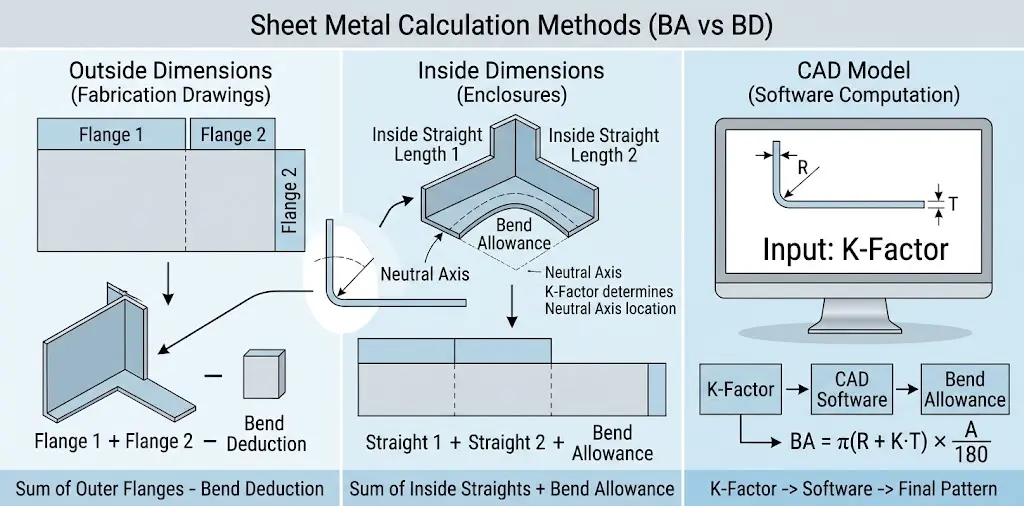
Bend allowance and bend deduction are the same neutral-axis geometry counted from opposite ends. They cannot disagree — provided each one is applied to the dimensioning scheme it belongs to.
- Outside dimensions (most fabrication drawings): sum the outside flange lengths and subtract one bend deduction per bend.
- Inside dimensions (common on enclosures that have to fit over something): add the inside straight lengths and one bend allowance per bend.
- CAD model: supply a K-factor and let the software develop the pattern internally, which is exactly how SOLIDWORKS documents it — pick K-Factor as the bend allowance type and it computes BA = π(R + KT) × A/180 from the K you supply.
The trap is not the arithmetic. It is the assumption that BA can be added to any number labelled “inside”. Bend allowance is an arc length measured along the neutral axis, and it can be added to a straight length only when that length is measured to the same reference the arc starts from — the tangent point. Dimensions given to a face, to a mould line, or to a virtual sharp are not that reference. Confirm what the callout actually measures before choosing the route.
The K-Factor: What It Is and What It Isn't
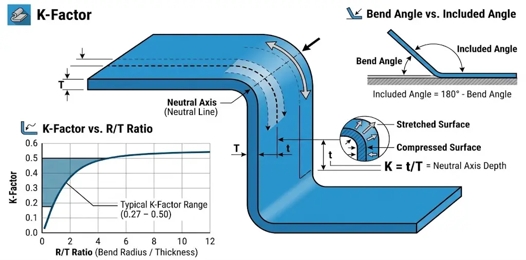
When sheet bends, the outer surface stretches and the inner surface compresses. Somewhere between them is a fibre that does neither — the neutral axis — and its length is the length the flat blank must contain. The K-factor is that fibre’s depth from the inside face, expressed as a fraction of the material thickness: K = t/T.
What the K-factor is not is a material constant stamped into the alloy. It moves with the ratio of inside radius to thickness, with the forming method, and with the tooling. Ansys puts the limitation plainly in its sheet metal documentation: the K-factor is a geometric calculation that does not account for the physical factors of a given bend process — material, operation, tools — so the only way to know the actual value for a setup is to reverse-calculate it from a real bend. Two numbers bracket the useful range, and each comes with a boundary rather than a law.
- 0.50 is the edge of the conventional model, not a physical tripwire. In the standard geometric treatment the neutral axis approaches mid-thickness as the inside radius grows to roughly four times the material thickness, and calculated values stay at or below 0.50. Ansys’s help documents exactly that curve: K rises to about 0.5 near R/T ≈ 4 and does not increase beyond it. If a calculation returns a value above 0.50, do not simply clamp it and carry on — re-check the angle convention, the radius, the thickness and the assumptions behind the K model you selected before the number reaches production.
- The floor for normal air bends sits near 0.27. Both the press brake literature and Ansys arrive at K = (4 − π)/π ≈ 0.273 for a bend radius equal to material thickness. Benson builds on that floor with a linear interpolation for air-formed mild steel: K ≈ 0.273 + 0.0756 × (R/T), which returns about 0.35 at R/T = 1. That linear form is an empirical approximation under one set of conditions, not a universal K-factor equation. It reaches the 0.50 line somewhere near R/T ≈ 3, it is not meant to be extrapolated past that, and other materials, dies and forming methods will not follow it. Use it as a starting estimate and verify against the material, tooling and process actually on the machine.

That is also why the equation and the chart in the trade literature do not quite agree: one curves to 0.50 at R/T ≈ 4, the other climbs in a straight line and arrives a little earlier. The difference is small next to the practical point — neither is a model to push beyond its range.
The famous 0.4468 figure belongs to the same body of work. It is the baseline K Benson embeds in the degree-based BA formula — BA = [(0.017453 × R) + (0.0078 × T)] × bend-through angle — where 0.0078 is π/180 × 0.4468. It is a convention, not a property of your steel.
CAD packages ship their own defaults, and it pays to know what they are. PTC’s Creo help defines the companion Y-factor as K × π/2 and ships a default Y factor of 0.50 — a software default, not material data. Dassault’s own SolidPractices guide for sheet metal is more candid still: in a default installation, SOLIDWORKS assigns a single bend allowance value to the whole part regardless of bend angle and bend radius. That default is a placeholder waiting for your shop’s numbers.
One more convention trips people up: the angle itself. The bend allowance formula uses the bend-through angle — also called the angle of rotation, measured from the original flat sheet. If a drawing specifies the included angle between the two finished flanges, convert it before calculating: bend angle = 180° − included angle. A 120° included angle is a 60° bend-through angle. A 90° bend is the special case where both values coincide, which is exactly why angle-convention errors go unnoticed on right-angle work and then surface on the next open bend.
Where Each Calculator Input Comes From
A bend allowance calculator is only as good as the six values fed into it. This audit table maps each input to its legitimate source, the entry that most often wrecks the result, and what the wrong blank does downstream.
The last row deserves emphasis, because it is the classic scrap-maker. Bend allowance and bend deduction are two bookkeeping systems over the same neutral-axis geometry, not two opinions. Applying the one that does not match the drawing’s dimensioning style shifts every bend by the full deduction amount — a large, consistent, and entirely avoidable error.
One Part, Three Routes, One Answer
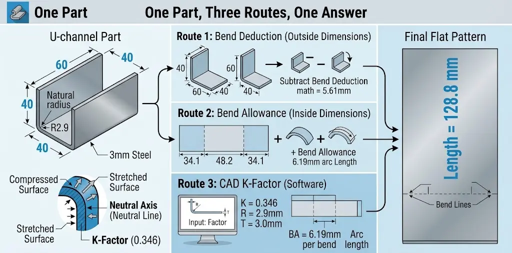
Consider a job any shop could run this week — a worked example built on an engineering approximation, not on measured production data. Nothing here was cut or bent; the arithmetic and the cross-check are the point, not the specific millimetres. A U-channel in 3.0 mm mild steel, two 90° bends, 60 mm outside width, 40 mm outside flange height, drawing calls out R3 inside radius maximum. The shop air-bends it over an 18 mm V-die (6t) with a sharp punch, so the natural radius the die produces is approximately 0.16 × 18 ≈ 2.9 mm — inside the R3 max callout, so the die on the machine wins and 2.9 mm goes into the math.
For the purposes of the example the K-factor comes from Benson’s interpolation: R/T = 2.9/3 ≈ 0.97, so K = 0.273 + 0.0756 × 0.97 ≈ 0.346. On real tooling that value would be replaced by one measured on the material and die in use.
Now the same part through the three routes:
All three routes close at 128.8 mm because they are the same geometry wearing three accounting systems. That closure is not a curiosity — it is a verification tool. If the BD route and the BA route disagree on a real job, one of the inputs is inconsistent: a radius entered on one route but not the other, an included angle entered as a bend angle, or a dimension reference mistaken for another.
One condition makes the BA route valid, and it is easy to skip: the straight lengths must be defined consistently with the neutral-axis development. Adding a bend allowance to a length that does not terminate at the bend tangent point is not a calculation error that shows up in the arithmetic — it is a modelling error that only shows up in the part. Confirm whether the dimensions terminate at tangent points, at inside surfaces, or at some other reference before you add anything to them.
The routes catching each other is the cheapest quality check in flat-pattern work, and it needs nothing but the calculator you already use.
How Big Can the Error Get?
The K-factor’s plausible range sounds small — 0.27 to 0.50 — but it translates directly into blank length. On the channel above, swapping the K while holding everything else constant gives:
The second row is the instructive one. A “typical” K value copied from a material-keyed table overshoots this part by nearly a millimetre, because the table never saw the R/T ratio. This channel is bent at R/T ≈ 1, where air-forming estimates put K near 0.35 — well below the generic 0.41–0.45 range those tables print for mild steel. Material-keyed tables are not wrong; they are incomplete. When the radius-to-thickness ratio is unusual, the ratio, not the alloy, drives K.
Scale that per-bend error across a real part. Two bends on this channel turn 0.9 mm of bad K into 1.8 mm of accumulated length error. On a four-bend enclosure the error doubles again, and after bending it stops being a length error at all — it becomes hole-to-edge distance error and tolerance stack in the finished part. A blank that is 3 mm long on a multi-bend cabinet does not fail at the press brake; it fails at assembly, where fixing it costs the most.
The angle convention fails faster at open bends. Take a 120° included angle — a 60° bend-through angle. Entering 120° where the formula wants 60° exactly doubles the allowance and inflates the setback threefold, because tan(60°) = 1.732 while tan(30°) = 0.577. The bend deduction, being 2 × OSSB − BA, swings with it. Right angles hide the mistake; open bends advertise it.
All of these numbers assume the stated geometry — 3.0 mm mild steel, an 18 mm die, a verified 2.9 mm formed radius. They demonstrate magnitudes and directions, not guaranteed results; the first article on actual tooling remains the referee.
What No Calculator Can Tell You
Three things sit outside any bend allowance formula, and each one produces blank-length symptoms that look like calculation errors but are not.
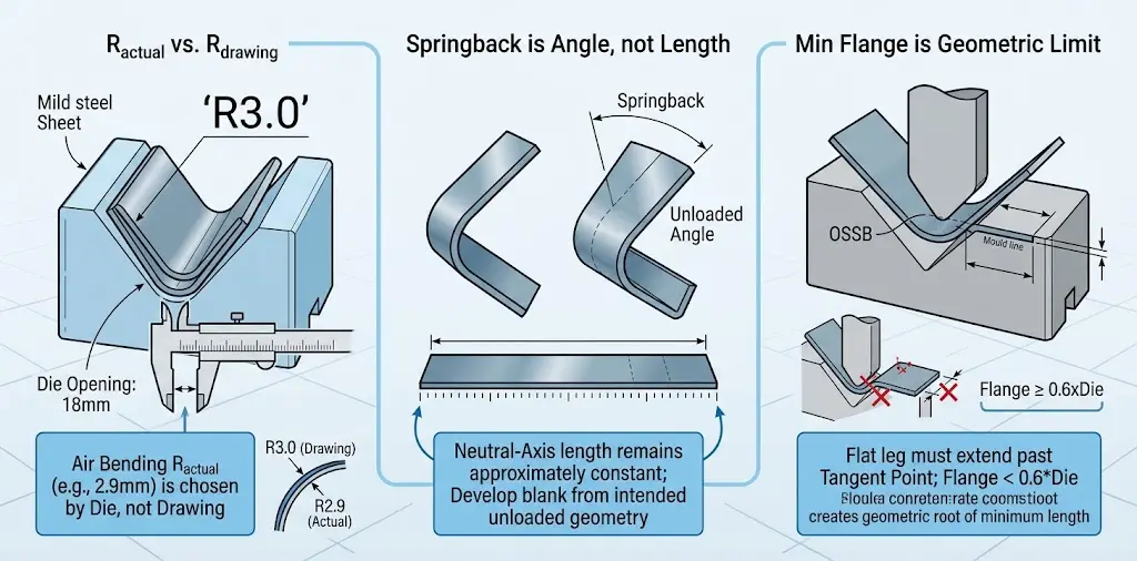
The radius the die actually forms. Air bending selects the inside radius from the tooling, not from the drawing. A shop that calculates BA from the drawing’s R3 while its 18 mm die delivers 2.9 mm is arithmetic-correct and physically wrong — the same part calculated on a 24 mm die needs a different allowance for the same drawing. How to choose the opening in the first place is the subject of our V-die selection guide, and the radius-to-die relationship is the single most consequential input in the whole table above.
Springback changes the angle, not the blank. Springback primarily changes the finished bend angle and radius, not the material length consumed by the bend. In a simplified bending model the neutral-axis arc length stays approximately constant through elastic unloading while the angle opens and the radius grows — which is why flat-pattern development and angle compensation are separate jobs. Real bending also involves plastic flow, tool contact, friction and non-uniform stress, so treat that relationship as the model it is rather than a guarantee. Develop the blank from the geometry of the intended unloaded part, correct the angle through the bending program or process settings, and verify both the finished angle and the flange dimensions on the first article. Our springback guide covers prediction and compensation in depth.
The setback is also a flange limit. OSSB measures from the mould-line apex to the tangent point, and the flat leg must extend past that tangent or the bend has nothing to grip and form against. This is the geometric root of minimum flange length — why a flange shorter than roughly 0.6–0.7 × the die opening fights you at the brake, independent of what the calculator says the blank length should be.
Your Controller Controls Angle, Not Your Flat Pattern
Here is the distinction that saves the most diagnostic time in a modern shop: in many press brake workflows the K-factor is consumed during CAD or CAM flat-pattern development, while the CNC control executes the bend from its own machine, tooling and material data. The exact division of work depends on the software and controller configuration — integrated systems exist that import a model, unfold it, and calculate bend allowances or deductions themselves, and many advanced controls support programmable springback compensation and per-bend angle correction. The centre of gravity is still the same: the control is landing an angle, not vouching for your blank.
That split gives the shop a clean way to sort symptoms:
Read the second row carefully. The controller did exactly what it was asked; it was handed a blank that disagreed with the finished geometry. That is the flat-pattern failure mode, and it surfaces as flange dimension errors — a defect with its own diagnostic path, not a bending problem to be tuned away at the control.
Keeping both sides consistent is a data problem, and it is where offline software earns its keep. When the offline programming environment, the CAM bend table and the controller database all carry the same K and BD values for the same material–die combination, the flat pattern the laser cuts and the program the brake runs finally describe the same part. Our software support team sets up and maintains exactly that link between design data and machine programs — and on unusual geometry, a coherent offline workflow beats heroic first-article guessing.
The one conclusion worth carrying out of this section is narrow and reliable: a correct bend angle does not automatically guarantee a correct flat blank, and a correct flat pattern does not guarantee a correct angle. Verify both, separately, on the first article.
Ranking the Sources for K
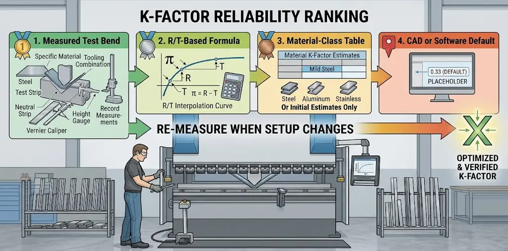
When a shop needs a K value, four sources exist. They are not equally trustworthy, and pretending they are is how a placeholder ends up governing production.
- A measured test bend on your own material, die and machine. Bend a strip at production settings, measure the formed result, and back-calculate the K that reproduces it. This is the only source that reflects the actual setup, and it is the standard against which every other value gets judged. The full procedure — strip count, measurement, and the record that makes the value reusable — belongs to flat-pattern practice as a whole, and we treat it in depth in our sheet metal bending guide.
- A published R/T-based formula, applied within its stated conditions. Benson’s interpolation is one such approximation for air-formed mild steel; it at least accounts for the variable that matters most.
- A material-class table, used as a starting point only — and re-checked whenever the radius-to-thickness ratio departs from the range the table assumed.
- A CAD or software default. A placeholder. Useful for a first concept model, not for a production blank.
One rule keeps all four honest: re-measure whenever the setup changes. A new die, a new material lot, a different machine or a different forming method each invalidate the old value, because the value never belonged to the material alone — it belonged to the combination.
Frequently Asked Questions
Conclusion
Bend allowance and the K-factor are not exotic math — they are bookkeeping for one geometric fact: the neutral axis keeps its length while everything around it stretches and compresses. The craft lies in feeding the calculation honest inputs — the radius the die actually forms, the thickness the micrometer reads, a K measured for the combination doing the work — and in matching the calculation route to the way the drawing is dimensioned.
Shops that treat the flat pattern as process data — verified by a test bend, stored against the tooling that produced it, and carried consistently from CAD to controller — cut blanks that form into parts the first time. If you are building a bending operation where the numbers hold up between design and machine, browse our press brake range or contact our team; we help customers set up tooling, software and controls so the part that leaves the CAD screen is the part that leaves the brake.