An electrical enclosure is easy to bend and hard to make fit. Doors that will not close, gaskets that never touch the flange, covers that rock on a body that was welded square — those are the complaints that reach the shop floor, and none of them is solved by a bigger machine.
Four numbers decide the specification, and tonnage is the least important of them: the longest bend you form, the largest cross-section that has to pass between the uprights, the deepest return flange the ram must clear, and the angle you can repeat at the foot of a two-metre wall. A 3 mm panel across 3.1 m asks for about 70 tonnes. Most cabinet work asks for less than 50. What a 150-tonne machine cannot do is hold a door gap if the bed deflects and nothing compensates for it.
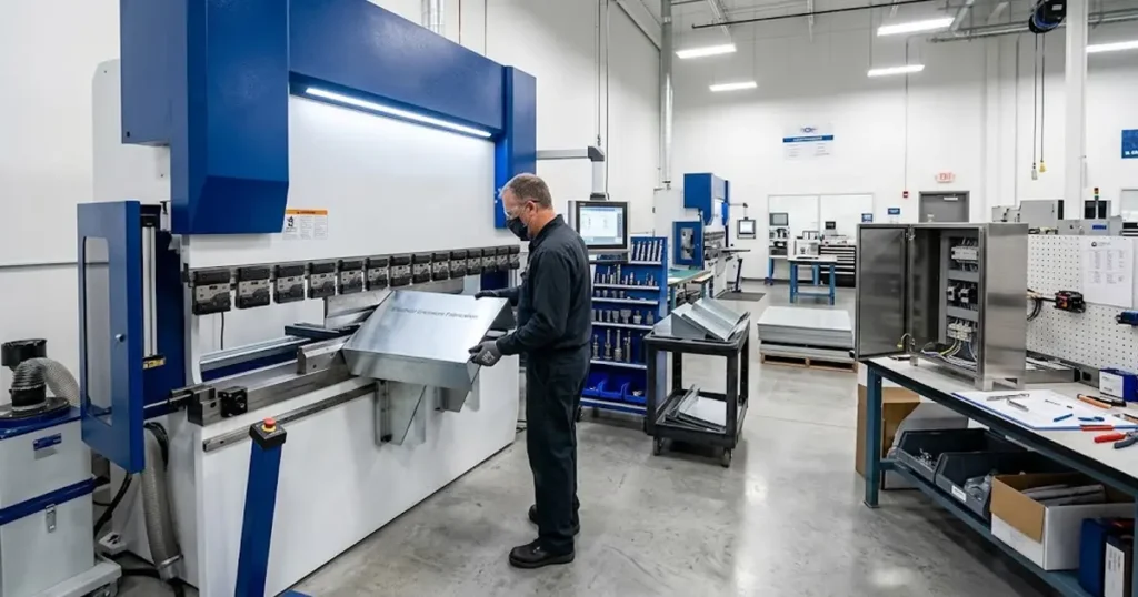
The six symptoms below cover almost every assembly failure in an enclosure shop. Each one traces to a specific mechanism, and each mechanism is fixed by a decision made before the machine is ordered — not by capacity.
| What the shop sees | What is actually happening | What fixes it |
|---|---|---|
| Door gaps differ from cabinet to cabinet | The angle is not wrong, it does not repeat | Program repeatability, then angle correction in the control |
| Top of a tall door stands off the frame | Door and opening disagree across a 2 m lever | One program for both parts, plus crowning set for the job |
| Second bend impossible on a box body | The part will not pass between the uprights | Specify on upright spacing, not on nominal bed length |
| Ram or punch body hits a standing wall | Daylight is smaller than tooling stack plus box depth | Gooseneck punch, and enough open height |
| Flange edge is bowed, gasket leaks mid-span | Bed deflection changes the angle along the bend line | Crowning calculated per part, not left at one setting |
| Zinc or paint cracked on the outside of the fold | Outer-fibre strain exceeds what the coating was qualified for | Open the die; check the coil's bend test result |
Enclosures Rarely Run Out of Tonnage
Air-bending force scales with the square of thickness and inversely with die opening, which is why thin-gauge work is undemanding and why so many enclosure shops overbuy. Using the common metric approximation
P (kN) ≈ 1.33 × σb × t² × L / V
with σb = 450 MPa for mild steel, 90° air bending and the die opening at 8 × t rounded to the nearest standard size, enclosure gauges land where you would expect:
| Thickness | Die opening | Force per metre | Tonnes for a 2.0 m bend | Tonnes for a 3.1 m bend |
|---|---|---|---|---|
| 1.2 mm | 10 mm | 8.8 t/m | 18 t | 27 t |
| 1.5 mm | 12 mm | 11.4 t/m | 23 t | 35 t |
| 2.0 mm | 16 mm | 15.3 t/m | 31 t | 47 t |
| 2.5 mm | 20 mm | 19.1 t/m | 38 t | 59 t |
| 3.0 mm | 24 mm | 22.9 t/m | 46 t | 71 t |
| 4.0 mm | 32 mm | 30.5 t/m | 61 t | 95 t |

Assumptions: 450 MPa tensile, 90° air bend, load distributed over the full bend length. The 1.33 coefficient is an approximation; charts using 1.42 return roughly 7% more. Neither changes the conclusion at these gauges.
A full-height switchgear side panel at 3 mm still asks for under 75 tonnes. The reason enclosure shops do not buy on tonnage is that tonnage is not what stops them — length is. A 300-tonne machine with a 2 m bed cannot bend a 2.4 m panel, and no amount of pressure compensates.
Two load rules matter at the margin. Keep the loaded bend length above roughly 60% of the distance between the side frames when you are near the machine’s rating. And remember that capacity is a per-metre figure: 110 tonnes over 3.2 m is 34 t/m, not 110 t/m. A 4 mm mounting plate bent over 300 mm is a 9-tonne job, trivial against a 110-tonne rating — but the tool section in contact is still carrying 30 t/m, and that is the number the die and the clamps have to survive.
The Enclosure Rating Sets the Bending Requirement
Electrical enclosures are classified by environmental type, and that classification is what makes one cabinet a tab-and-slot box and the next a gasketed, seam-welded shell. In North America the reference is NEMA 250, which defines Types 1, 2, 5, 12, 12K and 13 for indoor use and Types 3, 3X, 3R, 3RX, 3S, 3SX, 4, 4X, 6 and 6P for indoor or outdoor use (NEMA enclosure types).
Read the definitions as forming requirements and the machine consequences appear:
| Type | What the enclosure must resist | What it means at the press brake |
|---|---|---|
| 1 | Access to hazardous parts, falling dirt | No gasket. Flatness is cosmetic; a 1° flange is acceptable |
| 12 / 12K | Circulating dust, lint, dripping and light splashing water | A gasket land appears, so the flange must be flat and parallel all the way round. 12 has no knockouts, 12K does |
| 13 | Oil and non-corrosive coolant spray, splash and seepage | Machine-tool cabinets. The gasket line has to survive coolant, so the land cannot be interrupted by a die mark |
| 4 | Windblown dust, rain, splashing and hose-directed water | Continuous weld plus a compressed gasket — a flat land is now a sealing surface with a defined compression range |
| 4X | Type 4 plus corrosion resistance | Stainless, aluminium or coated substrate, which changes radius, springback and tooling |

One nuance decides how much of the tolerance burden bending should carry. NEMA describes these types “in general and functional terms” and deliberately omits structural detail — it tells you what the finished enclosure must resist, not how to build it, and not how to bend it. The gasketed door, the continuous weld and the flat sealing land are industry practice for reaching the rating, not clauses in the standard.
That places bending tolerance correctly. The rating applies to the assembled enclosure, and bending is one contributor in a chain that also includes weld distortion, hinge adjustment, hardware pull-out and coating build. A shop chasing bend angle to zero while welding a door frame with visible distortion has optimised the wrong link. What bending owes the assembly is a flange plane that is flat, parallel and repeatable — an angle-consistency requirement, not a dimensional one.
The Tolerance That Decides Whether the Door Shuts
Angular error at a bend does not stay angular. It becomes a linear error at the end of the flange, and the lever arm is the flange length:
deviation ≈ L × tan(θ)
| Flange length \ Angle error | 0.25° | 0.5° | 1.0° |
|---|---|---|---|
| 50 mm | 0.22 mm | 0.44 mm | 0.87 mm |
| 100 mm | 0.44 mm | 0.87 mm | 1.75 mm |
| 150 mm | 0.65 mm | 1.31 mm | 2.62 mm |
| 200 mm | 0.87 mm | 1.75 mm | 3.49 mm |
| 300 mm | 1.31 mm | 2.62 mm | 5.24 mm |

The table only becomes useful once you fix which length L is. On a 200 mm door return, half a degree costs 1.75 mm, which a gasket of normal section absorbs. On the 2000 mm side wall of a floor-standing cabinet, the same half degree puts the top edge 17 mm from nominal.
Here the absolute error is not what breaks the build. What breaks it is disagreement: form the door to one setting and the opening to a setting half a degree different, and the top of that door stands 17 mm off the frame while both parts pass inspection on their own. That is a repeatability failure, not an accuracy failure, and it is why a shop can hold ±0.5° on every part and still ship cabinets that do not close.
Run the arithmetic the other way and the requirement appears. If a 2 m edge must land within 2 mm, the angle has to repeat to about 0.06°, part to part:
required repeatability ≈ arctan(2 ÷ 2000) ≈ 0.06°
That is an order of magnitude tighter than the ±0.5° on a datasheet, and it is not a contradiction. A datasheet figure describes per-bend accuracy at the ram under reference conditions — Y1/Y2 repeatability, valve response, depth resolution — and a machine holding ±0.5° absolute is doing well. The remaining gap is closed by removing errors that are not random, and the largest of those is deflection: a deterministic function of load, length and frame stiffness, which is exactly what makes it compensatable.
Three mechanisms attack the residual, in order of effect:
- Crowning set for the job, not fitted as an option. Mid-span versus end angle difference is a deflection signature, so compensation must be calculated from the load and length of the part actually in the machine. A multi-point crowning system driven from the control does that per program; a crowning table left at one setting does not.
- Angle correction in the control, so the residual after compensation is trimmed against a measured result rather than an operator’s judgement. In-process angle measurement turns door fit into a closed loop instead of a trial bend.
- A backgauge that repeats, because flange length is the lever arm in the first table: 0.1 mm of gauge error on a 200 mm flange is 0.03° of angle error, which is nothing; 0.5 mm is 0.14°, which is not.
Where the two ends of a bend sit at different angles from the middle, the flange edge is not merely displaced — it is no longer straight, and straightness is what a gasket land is judged on.
Machine Specs by Enclosure Class
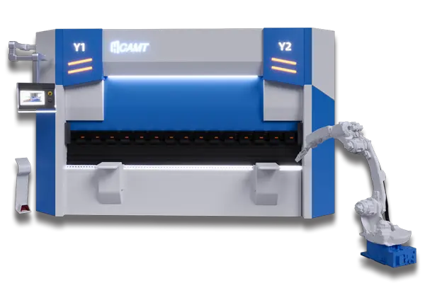
The table maps the common enclosure classes to a configuration that will produce them, using the CAMT Genius range’s published model set as reference points. Figures in brackets are nominal capacity and bed length.
| Enclosure class | Gauge | Longest bend | Capacity | Bed | Uprights | Open height | Axes |
|---|---|---|---|---|---|---|---|
| Junction, pushbutton, terminal boxes | 1.0–1.5 mm | ≤ 600 mm | 40–70 t (40T/1600, 70T/1600) | 1.6 m | 1.2 m | 450–460 mm | 3 (Y1, Y2, X) |
| Wall-mount enclosures, 600–800 wide | 1.2–2.0 mm | 1.0 m | 70–110 t (70T/2500) | 2.5 m | 2.0 m | 460 mm | 3–4 (+ R) |
| Floor-standing cabinets to 2000 high | 1.5–2.5 mm | 2.0 m | 110–130 t (110T/3200) | 3.2 m | 2.7 m | 490 mm | 4 (+ Z1/Z2) |
| Multi-bay switchgear, long side panels | 2.0–3.0 mm | 3.0–4.0 m | 170–250 t (170T/4100, 250T/4100) | 4.1 m | 3.3 m | 490–540 mm | 4–6 + crowning |
| Cable trough, 6 m sections | 1.5–3.0 mm | 6.0 m | 220–300 t (220T/6000, 300T/6000) | 6.0 m | 5.0 m | 500–635 mm | 4–6 + crowning |
| Mounting plates, brackets, busbar supports | 3.0–4.0 mm | ≤ 1.5 m | 70–110 t (70T/1600, 110T/2500) | 1.6–2.5 m | 1.2–2.0 m | 450–490 mm | 3–4 |
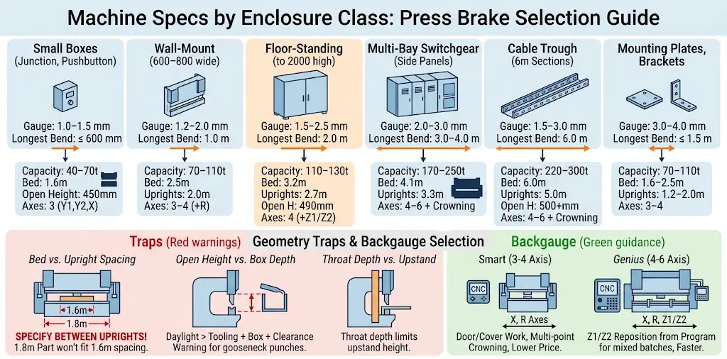
Three geometry traps are hidden in that table, and each one has caught a buyer.
Bed length versus upright spacing. A machine advertised with a 2.0 m bending length may have its frames set at 1.6 m. A 1.8 m cabinet side will not sit between them, so the second bend cannot be formed at any tonnage. Specify on the distance between uprights for any part that has to pass through the frame, and add clearance for flanges already formed. This is why a 2 m floor-standing cabinet normally lands on a 3.2 m bed rather than a 2.5 m one.
Open height versus box depth. Daylight has to cover the tooling stack, the box depth and removal clearance. A 200 mm deep body on a 120 mm tooling stack needs more than 320 mm of open height before you add margin for tilting the part off the punch. Deep bodies also force a gooseneck, which shortens the punch body but does not reduce the daylight requirement.
Throat depth versus upstand. Throat depth limits how far a formed wall can pass behind the tooling. Thin-gauge enclosure work rarely needs more than 300–400 mm, but a deep return on a large section can exceed it, and rotating the part to re-datum costs more than the throat would have.
Backgauge axes deserve the same discipline. Three axes — X, R and one Z — cover most door and cover work, because an offset cutout or a stepped flange needs lateral repositioning between bends. A fourth axis (independent Z1/Z2) pays back only where parts change often enough that the operator’s manual finger-setting time is visible in the day. The axis combinations are set out against part types on our backgauge selection page.
For shops whose parts never need lateral repositioning and whose largest panel is under 2.5 m, the Smart 3–4 axis synchronous press brake covers the same work from 40 to 600 tonnes and 1.6 to 6 m with X and R axes and multi-point crowning, at a lower price than a six-axis machine. The Genius 4–6 axis CNC press brake is the step up for mixed batches, where Z1/Z2 reposition to the next part’s dimensions from the program instead of the operator resetting stops by hand. Price both against your actual part list rather than against a preference for axis count.
Tooling: Four Decisions and One Sequence
Enclosure tooling is not exotic. It is a small set, chosen deliberately and pre-staged so that changeover is a lift rather than a rebuild.
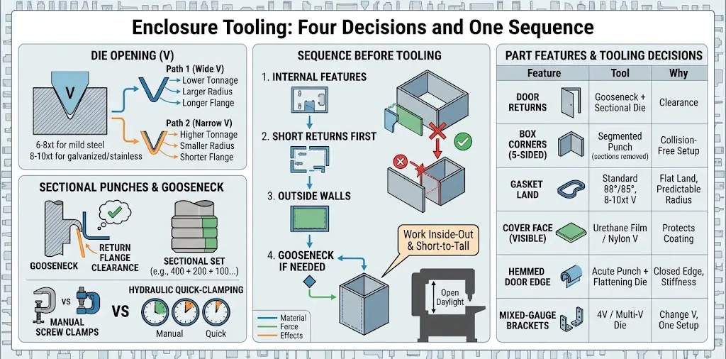
Die opening. 6–8 × t is the working range for mild steel, with 8 × t the better default on enclosures because the wider opening forgives thickness variation and gives a radius that does not fight the coating. Go to 8–10 × t for galvanized, prepainted and stainless. A wider V means lower tonnage, a larger inside radius and a longer minimum flange — three effects that must be accepted together, because they come from the same geometry.
Sectional punches and a gooseneck. Segmentation lets you remove the section that would collide with a return flange already formed. A standard 835 mm set splits into 400 + 200 + 100 + 50 + 40 + 20 + 15 + 10 mm, which covers the great majority of box and door work. A gooseneck buys height clearance at the punch body, which is what a return flange on an enclosure wall needs in order to pass under the ram.
Sequence before tooling. An enclosure body is a box, and a box is a sequence problem: the order in which the walls go up decides whether the tooling can reach the last bend at all. Work inside-out and short-to-tall, forming internal features and the shortest returns first, so each new bend has the least material standing in the way. When a wall height approaches the punch body clearance the gooseneck becomes mandatory, and when it approaches open height minus tooling stack the machine is simply too small. Our guide to bending deep boxes and cabinets without tooling interference works through the sequence logic; the point here is that sequence has to be settled before the machine is specified, because both the machine and the tooling are chosen to make the sequence possible.
Edges that get handled. A door edge is normally hemmed for stiffness and for the person who lifts it. That is a separate operation with its own tooling — an acute punch and a flattening die, or a dedicated hem tool — and it belongs in the tooling budget from the start rather than being discovered at the first production run.
| Part feature | Tool | Why it is right | What it costs |
|---|---|---|---|
| Door and cover returns | Gooseneck punch + sectional die | Clearance for the flange already formed | Lower load rating than a straight punch of the same height |
| Box corners on a five-sided body | Segmented punch, sections removed | Removes the collision without a special tool | Setup discipline; sections must be logged |
| Gasket land on a door | Standard 88°/85° tooling, 8–10 × t V | Flat land, predictable radius, tolerance to gauge variation | Slightly larger radius than a tight V |
| Visible cover face | Urethane film or nylon V insert | Protects coating and paint | Reduced load capacity, faster wear |
| Hemmed door edge | Acute punch + flattening die | Closed edge, stiffness, no sharp burr | Extra station, extra pass |
| Mixed-gauge brackets, one setup | 4V or multi-V die block | Change V without changing the die | Less usable bed length per station |
Two interactions are easy to miss. A gooseneck is shorter in its load-bearing section than a straight punch, so its rated tonnes per metre is lower — check the tool’s rating, not the machine’s. And a die block occupying 400 mm of bed removes 400 mm of usable length for that job. Clamping decides how fast any of this changes: manual screw clamps, hydraulic quick-clamping and pneumatic systems differ by minutes per setup, which is the difference between a viable high-mix shop and one that batches everything to avoid changeovers. Our tooling and tool storage and tooling clamping pages cover the options; the press brake tooling compatibility guide covers what actually interchanges between European, American and WILA-style systems before you buy a second set.
Galvanized and Prepainted Stock Changes the Die, Not Just the Tonnage
A large share of electrical enclosures is built from hot-dip galvanized sheet, and that substrate is ordered to a specification that already addresses bending. ASTM A653/A653M covers zinc-coated and zinc-iron alloy-coated sheet by the hot-dip process, sets out coating designations and weights, and requires that “a bend test shall be done to the coated sheets” (ASTM A653/A653M). Coating adhesion at a bend is therefore a specified property, not luck: if zinc is flaking off the outside of the fold, either the material is outside the designation that was ordered or the process is asking for more strain than the coating was qualified for.
Strain is the useful way to think about it, because it is calculable. For an air bend where the inside radius floats at a fraction of the die opening, the outer surface stretches by approximately
ε ≈ t / (2R + t)
where R is the inside radius and t the thickness. The radius follows the die opening: for mild steel it floats at roughly 15–17% of V, and for 304 stainless at 20–22% (The FABRICATOR). Put the two together and die opening stops looking like a convenience choice:
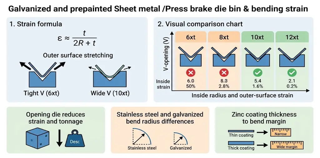
| V / t | Inside radius, mild (≈16% of V) | Inside radius, 304 (≈21% of V) | Outer-surface strain, mild | Tonnage index (8 × t = 100) |
|---|---|---|---|---|
| 6 | 0.96 × t | 1.26 × t | ≈ 34% | 133 |
| 8 | 1.28 × t | 1.68 × t | ≈ 28% | 100 |
| 10 | 1.60 × t | 2.10 × t | ≈ 24% | 80 |
| 12 | 1.92 × t | 2.52 × t | ≈ 21% | 67 |
| 16 | 2.56 × t | 3.36 × t | ≈ 16% | 50 |
Strain is ideal pure-bending geometry at the outer fibre. Real air bending concentrates additional strain near the die shoulders, so treat the column as a comparison tool rather than a pass/fail limit. Whether a given coating survives is answered by the coil’s bend test result and by a trial bend.
Three consequences follow.
Opening the die is the first move, not the last. Going from 6 × t to 10 × t drops outer-surface strain by nearly a third and cuts required tonnage by 40%. On galvanized work that is usually enough to stop visible cracking without changing material.
Stainless and galvanized parts do not interchange, even at the same gauge. At 8 × t, 304 forms an inside radius about 30% larger than mild steel does. The bend deduction moves with it, so a door cut from a flat pattern developed for galvanized will not match a door formed from 304 on the same die. Where a Type 4X variant shares a flat pattern with a Type 12 variant, that flat pattern is wrong for one of them.
Thicker coating buys corrosion and spends bend margin. A heavier zinc designation protects longer and tolerates less at a tight radius. Where the specification drives both — an outdoor enclosure with a small corner radius — fix the radius first, let the coating designation follow, then confirm with the coil supplier and a trial bend.
Surface Quality Is a Materials Problem Before It Is a Tooling Problem

Galvanized. Zinc is soft and transfers to die shoulders under pressure, building up and then marking every part that follows. Clean the shoulders on a schedule rather than when a defect appears, use 8–10 × t, and run urethane film on visible faces. The cut edge belongs to the same corrosion system: a sheared or laser-cut edge with a burr concentrates strain and starts the crack the coating then follows, so deburring before forming is not cosmetic on a visible galvanized panel.
Stainless. 304 carries a tensile strength well above the 450 MPa used for mild steel, so expect roughly 1.3–1.5 times the tonnage at the same thickness, plus more springback that has to be absorbed by the control rather than by the operator. It also shows handling marks that galvanized hides, which means protective film, polished tooling or nylon inserts from the first part — not after the first rejection.
Prepainted and powder-coated. Coil coating fails by strain at the bend line, and the coil carries a T-bend rating that states what it will take. Decide the sequence before the machine and tooling package are fixed: bend-then-coat removes the cracking risk but puts the bend radius and the weld into the finish schedule; coat-then-bend is cheaper per part and depends entirely on radius, film build and the insert you put on the die. A shop that has not answered this question cannot specify a die opening.
Production Volume Changes the Setup, Not the Machine
Machine size is set by the part. Volume sets only how fast you change over and how much of the day the machine is stroking — which is why the volume question belongs after the geometry question, not before it.
| Production pattern | What to buy | Where the money goes |
|---|---|---|
| 20–200 off, many models (job shop, custom panels) | 3-axis machine sized on the longest bend, sectional tooling in holders, gooseneck | Tooling inventory and a staged holder system. Axes beyond Z rarely pay |
| 200–2,000 off, a dozen cabinet families | 4-axis with Z1/Z2 and crowning, quick clamping, offline programming | Changeover time: clamping, program library, tool height standardised across the set |
| 2,000+ off, one standard design | Dedicated tooling per part, assisted handling, and a serious look at a panel bender | Handling and cycle time, not machine sophistication |
The test for any option is arithmetic, not preference. Count setups per week and multiply by the minutes an option removes. A Z axis that saves four minutes on each of 30 setups a week returns 2 hours a week — 100 hours a year — and that either justifies the option at your labour rate or it does not.
When a Press Brake Stops Being the Right Answer
Some enclosure manufacturers should price a panel bender alongside the press brake. The machine forms a panel from a flat blank with tools working above and below it, so a four-sided box body can be produced without turning the part over between bends.
| Factor | CNC press brake | Panel bender |
|---|---|---|
| Multi-sided panels | Needs a sequence, a gooseneck and manual handling between bends | One handling, all four sides formed from the program |
| Part envelope | Limited by bed length and upright spacing, but a long bed covers most enclosures | Limited by the machine's blank size; a 3 m side panel changes the price class |
| Deep boxes and tall returns | Handled with the right punch and daylight | Limited by the forming tool geometry; deep bodies often fall outside it |
| Small brackets and one-off parts | The natural tool | Awkward — small blanks are outside the handling envelope |
| Thick or high-strength plate | No practical limit within machine rating | Typically falls outside the working range |
| Tooling | Broad, interchangeable, cheap to extend | Proprietary forming tools, slower to add a new geometry |
| Best fit | Mixed production, varied geometries, thick or unusual parts | One family of similar panels at volume |
For a job shop running many enclosure models, the press brake is the better investment and the panel bender is a second machine, not a replacement. For a manufacturer producing thousands of the same cabinet body, the panel bender can remove the handling that dominates the cycle — but the blank must fit, the box must be within the tool geometry, and the parts that are not that body still need the brake.
Five Mistakes That Survive the Capacity Chart
Ignoring the shortest flange until the die is chosen. A narrow V forms a short flange but raises tonnage sharply: the same 2 mm part needs 15.3 t/m at a 16 mm V and 20.3 t/m at a 12 mm V. Check the minimum flange and the tonnage together, or the die that solves the flange creates a capacity problem.
Reading machine tonnage as tool tonnage. A 110-tonne machine working across its full 3.2 m bed demands 34 t/m. Fit a gooseneck rated at 25 t/m and the tool sets the limit at 80 tonnes, not the machine. Goosenecks, nylon inserts and long die blocks all carry ratings below the machine’s, and the rating is per metre of contact rather than per job.
Assuming the next coil bends like the last one. Yield strength varies between heats and between suppliers within the same designation, and springback follows it. On a repeat job, keep a reference piece and a recorded angle-correction value; a new coil that needs 0.3° more correction is normal, and a shop without a reference chases it as a machine fault.
Buying axes you will not program. Every axis adds setup data. If nobody is going to enter the lateral position for each bend, the axis is a manual stop with a servo attached. Ask what the programmer will actually type, then justify the axis on that.
Accepting the machine on a simple part. Take the three hardest parts in the family — the deepest box, the longest side panel, the smallest gasketed door — and run them before sign-off. Interference, daylight and backgauge reach are all discovered on those three parts, and it is cheaper to discover them before the balance is paid.
Where to Start
An enclosure programme does not need a large press brake. It needs a long enough one, with the frame geometry to let the part in, crowning set for the job, and a tooling set that keeps the next changeover short. Get those four right and the door closes on the first try, batch after batch.
Send your part list through our contact page and we will size the machine on the longest bend and the largest cross-section, then tell you where the crowning and axis requirements land — rather than leaving you to work it out from a capacity chart.
The numbers in this article come from the allowances and bend geometry set out in our sheet metal bending guide.