A hem on a press brake is made in two stages: an acute-angle pre-bend that folds the edge back on itself, followed by a flattening stroke — or a dedicated hemming tool — that closes the fold to a flat, open, or teardrop profile. The pre-bend usually lands somewhere between 30° and 45°, and the closing hit works the metal closer to a coining operation than to an ordinary air bend, which is why hemming demands more from your tooling, your force calculations, and your material selection than the same thickness bent as a plain flange.
If you are planning a hemmed part, four things decide whether it runs cleanly or turns into a bottleneck:
- Hem profile — closed, open, or teardrop. The profile sets the closing force and the crack risk.
- Tooling setup — two separate setups, a combination tool, or a single-station hemming die, chosen by hem length, material, and volume.
- Material — mild steel closes easily; hard aluminum and thick stainless crack on closed hems and belong in teardrops.
- The flat pattern — a closed hem stretches the material by roughly 43 percent of the thickness under ideal conditions, and that elongation must be accounted for before the first blank is cut.

Why Manufacturers Use Hems
Hemming is widely used when a component needs a finished edge without additional welding, fastening, or separate edge protection:
- Operator safety: folding the exposed cut edge inward removes direct contact with sharp burrs.
- Edge stiffness: the doubled section resists local deformation along the hemmed edge.
- Appearance: a cleaner perimeter on visible panels and finished components.
- Assembly: a folded edge gives adjoining components a consistent contact surface — and open hems in particular can interlock parts without fasteners.
- Less secondary processing: in suitable designs, a hem replaces edge finishing or a separate joining operation.
Common applications include electrical enclosures, cabinet doors, automotive panels, HVAC components, appliance housings, and stainless architectural panels. John Kemp, bending product manager at Bystronic, went further in an interview with Canadian Industrial Machinery: hemming, he argued, is the most underutilized bending technique, because designers tend to think about how to join two pieces when a hem could make the part one piece instead. The observation matches shop reality — the shops that get the most from hemming treat it as a design feature decided at the drawing stage, not a finishing operation improvised at the brake.
The same shops also know hemming’s other reputation: a bottleneck. Two setups per hem, repositioning between hits, large panels lifted through the first stage, open hems formed around shims binding shut — most of these problems trace back to decisions made, or not made, before the job reached the brake.
The Three Hem Profiles: Closed, Open, and Teardrop
Different profiles serve different functional and manufacturing requirements, and the profile should be fixed before tooling is chosen — not discovered through production trial and error.
| Profile | Geometry after closing | Best suited for | Watch points |
|---|---|---|---|
| Closed (flat) hem | Edge pressed flush against the sheet; near-zero inside radius | Mild steel covers, doors, guards, sanitary food-service edges where no gap can be tolerated | Highest closing force; highest crack risk on hard tempers; marking risk on visible faces |
| Open hem | Fold stops short of full closure, leaving a defined gap | Crack-sensitive material, prepainted or finished panels, edges that interlock in assembly | Gap must be specified and controlled; long open hems formed around shims can bind shut |
| Teardrop hem | Fold closed around a rounded internal loop | Thick or hard stainless, aluminum, and any part where a dead-flat closure risks cracking | Loop size must be consistent; can trap fluids in some finishing processes |
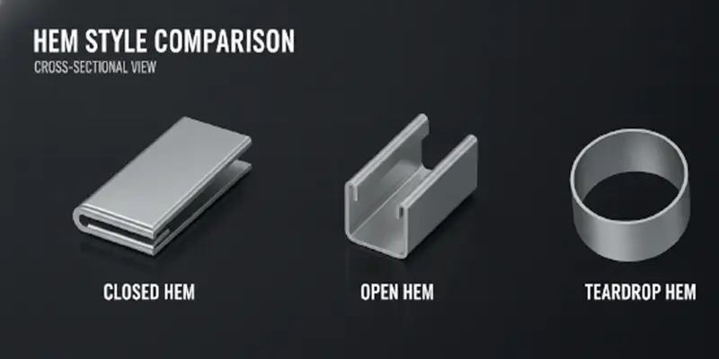
The closed hem is the most common, and the open hem a close second. Benson’s bend-functions column in The FABRICATOR adds a practical reason open hems have gained ground: the chemical processing common in today’s shops — passivation, chromate conversion, etching — leaves residues that are genuinely hard to flush out of a fully closed fold. If the part goes through plating or chemical finishing, an open or teardrop profile saves trouble downstream.
The teardrop deserves a specific endorsement from the tooling side. Larry Boden of Mate Precision Technologies calls it by far the easiest hem to fabricate: it takes less tonnage, causes less tool wear, and still gives the edge the same protection a closed hem does. Its main drawbacks are cosmetic and sanitary — chemicals can pool inside the loop — so food-service and wash-down parts usually justify the extra effort of a closed hem instead.
Stage 1: The Acute Pre-Bend

The first operation folds the sheet edge past vertical into an acute angle, commonly around 30° to 45° depending on the tooling, material, and target profile — the same window our press brake tooling guide gives for pre-hemming work. A suitable acute punch and V-die combination forms the bend; the outside surface works in tension and the inside in compression, so the radius must be large enough to keep strain in check on stainless, high-strength steel, and aluminum.
The pre-bend is a controlled intermediate geometry, not the final angle — but three details separate a clean pre-bend from one that sabotages the closing hit:
Match the inside radius to the finished hem. Boden’s guidance on the acute hit is blunt: you want the inside radius formed in the pre-bend to match the radius the finished hem needs. When the radius is wrong, the closing stroke crushes it unevenly, the edge rolls, contacts the parent sheet, and starts lifting at the ends — and the flatter you try to press it, the more it lifts. That lifted edge is more than cosmetic: it opens a gap sharp enough to be a cutting hazard. Also account for springback when targeting the pre-bend angle, and avoid an excessively sharp initial bend that will crack during closure.
Give the flange enough length. Acute-angle bends need somewhat longer minimum flanges than square bends. LeTang’s tool-selection rules in Canadian Metalworking put the 30° pre-bend minimum at 115 percent of the selected V-die opening — over a 0.375 in. die, a flange of at least 0.431 in. The full logic behind minimum flange length is covered in our article on the subject; for hem work it is worth reading before the blank is cut, because a hem flange that is too short has no recovery once the flattening hit is thrown.
Keep the angle consistent along the length. Whatever variation the pre-bend leaves in the flange shows up in the finished hem as an uneven gap. The V-opening behind the acute die follows the same selection logic as any other bend — our V-die selection guide covers that in depth — and if the angle is hard to hold along the part, the causes usually live in the setup rather than in the hemming process: that diagnosis path is the same one behind angle variation on any acute bend.
Stage 2: The Flattening Hit

After pre-bending, the workpiece is repositioned and the pre-bent flange is placed over the flat closing surface of a hemming die or flattening tool. The ram applies controlled pressure, progressively compressing the fold until it reaches the required profile — nearly closed, or deliberately open, depending on the drawing.
Two forces fight the operator during this hit: the angled sheet tries to slide the flattening bar sideways, and the workpiece itself tries to slide out of the die toward the operator. Tooling suppliers call these the thrust forces, and they grow most severe on thick material with short flanges — exactly the parts that are hardest to hold by hand.
Setup practice on flattening dies is mostly free-form. Operators place the pre-bent part against the lower die by eye, because backgauge fingers that could help steady the work during the ram approach have to clear the tool before the stroke. On longer or heavier panels, that hand positioning is where the ergonomic and safety burden concentrates — The FABRICATOR’s hemming-strategies feature describes shops where several people hold a large stainless panel in place while the tool closes the hem, and nobody pretends that is ideal.
How much force the closing hit needs depends on material strength and thickness, hem length, the initial radius and pre-bend angle, the die geometry, and above all the hem type. Open and teardrop hems barely change the inside radius — the stroke is essentially continuing the pre-bend — so they close at modest force. A closed hem is a different operation: flattening forms a crease, removes the inside radius, and works the metal rather than simply bending it, so the force climbs steeply with thickness.
Stage 3: Inspecting the Finished Hem
Inspect the edge before releasing the job to batch production:
- Hem closure: confirm the gap (or full closure) is within the specified tolerance.
- Edge straightness: check for waves, local bulges, and uneven closure along the bend.
- Surface condition: look for scratches, dents, coating cracks, or pressure marks.
- Dimensional accuracy: verify flange dimensions and the finished part geometry.
- Material integrity: inspect the outside of the fold for cracks or visible tearing.
Measure the gap or loop at several points along the hem rather than once in the middle, and establish measurable acceptance criteria rather than relying on visual judgment alone.
Hemming Dies vs. Standard V-Dies
One of the most common mistakes in press brake hemming is assuming an ordinary V-die can handle every flattening operation.
| Comparison | Standard V-Die | Dedicated Hemming Die |
|---|---|---|
| Main purpose | Conventional sheet bending | Edge folding and closure |
| Pre-bending | Possible with acute tooling | Designed into the tool |
| Flattening | Requires a separate closing setup | Built-in closing surface |
| Thrust control | None during flattening | Redirects closing forces into the die body |
| Setup | Tool changes between stages | Some designs combine multiple operations in one station |
| Typical application | General bending | Closed, open, and safety hems |
There is no universal rule that a dedicated hemming die is always required. Some workshops run a separate acute punch and a simple flattening bar — the standard approach for prototypes and short runs, since both tools earn their keep on non-hem work. What to avoid is improvising the closing hit under a standard punch shoulder: the flattening hit is an off-center, thrust-loaded operation, and tooling not designed for it can be kicked sideways or overloaded. A dedicated flattening bar or hemming tool is inexpensive insurance.
The right tooling arrangement is a function of hem length, material, and volume:
| Shop situation | Recommended setup | Why |
|---|---|---|
| Short runs, prototypes, mixed hem lengths | Two separate setups: acute tooling, then a flattening bar | No special tooling needed; slowest option per part |
| Short hems, matching shut heights | Stage acute and flattening tools in one setup | One handling; works when the hem is short enough to close between the tools |
| Hem longer than half the bed, or heavy hemming volume | Single-station hemming tool (spring-loaded or shelf-type) | Combines every hit in one toolset; no re-gauging between stages; the acute station doubles for plain acute bends |
| Thick or hard material, thrust-heavy parts | Thrust-absorbing hemming tooling; teardrop profile | Redirects closing forces into the die body; teardrop lowers required force |
| Large panels with hemmed edges | Flat-sheet (horizontal) hemming tooling, or a folding machine | Wiping action forms the flange with the sheet kept flat on the table; no lifting the panel through an up-bend |
Combination and multi-stage dies deserve a note on control. Because the first and second stages sit at different working heights, running them without programmable stroke control makes manual adjustment tedious — and running the wrong stage’s program against the wrong step is a documented way to break hemming dies. Boden’s tally of broken hemming tools comes overwhelmingly from that mismatch: the flattening step run as an acute bend, or the other way around. On a CNC press brake with programmable stroke and pressure, the two steps live in the program and the mismatch disappears.
Matching the Tooling to the Material
Material thickness sets the pre-bend geometry, the flange allowance, and the closing setup — and a die suited to one nominal gauge is not automatically suitable for every material in that gauge. Check nominal thickness, actual thickness tolerance, required inside radius, pre-bend angle, final profile, and the tooling’s working dimensions as a set.
Ductility decides the rest:
| Material | Hemming consideration |
|---|---|
| Mild steel | Generally suitable for conventional hemming when radius and tooling are appropriate |
| Stainless steel | Higher forming resistance and springback; surface protection matters |
| Aluminum | Alloy and temper strongly influence crack resistance |
| Galvanized steel | Excessive compression can damage the zinc coating |
| High-strength steel | Careful evaluation of forming force, radius, and material limits |
The aluminum row deserves specifics. Brown’s warning on 6061-T6 is categorical — take a hard aluminum and start hemming it and you will likely get cracking, even bending against the grain. If the drawing shows a closed hem on 6061-T6, the right move is to push back before the blank is cut and propose a teardrop. 5052-H32 is far more formable but not immune: Boden notes it still cracks when the hem operation stretches the material too far, which is a radius and process problem as much as a material one. For critical applications, test the actual material batch before approving the production setup.
Alignment and Surface Condition
Misalignment creates uneven contact pressure during flattening: if punch and die are not parallel, one side of the hem closes before the other, producing inconsistent gaps, local deformation, and visible marks. Before production, clean the contact surfaces, check tool seating and clamping security, verify upper and lower alignment, inspect the closing surface for wear, and confirm segmented tooling is correctly positioned. For long workpieces, straightness across the entire bend length matters most — and tooling must be compatible with the machine’s clamping interface, which is worth verifying before ordering replacement or custom tools.
How Much Force Does Flattening Require?

Hemming and flattening can require substantially more force than conventional air bending, because the material is compressed against a closing surface rather than formed through three-point contact. Conventional air-bending tonnage formulas rest on assumptions — die opening, three-point geometry — that do not describe a flattening operation. Do not use an ordinary air-bending result as the machine or tooling requirement for hemming: obtain the closing-force requirement from the tooling manufacturer’s application data or through a controlled trial.
As a scale reference, LeTang’s rule of thumb is that hems thicker than about 1/8 in. (roughly 3 mm) may need custom tooling to accommodate the excessive forces involved. Past that point, most shops redesign the edge as a teardrop or open hem instead of pushing a standard tool set past its rating.
Before committing any flattening hit, verify the load path: the press brake’s available force at the operating position, the allowable load of punch, die, holders, clamps, and machine structure, and the centerline limits that apply to concentrated or short-section loading. Our article on tooling load limits walks through that check in detail; the same reasoning that keeps a die intact on a heavy V-bend keeps a hemming die in one piece on a closing hit.
Important: never attempt to close a hem by simply increasing the CNC pressure setting. Establish the tooling’s load limits, verify the machine’s allowable operating conditions, and determine the closing parameters before production — and if a hem opens after flattening, the problem is usually geometry, not insufficient force.
Hemming Defects: Symptoms, Causes, and Fixes
This is the table to keep near the brake. Hemming defects cluster into a handful of patterns, and each has a usual suspect.
| Symptom | Most likely causes | First fixes |
|---|---|---|
| Cracks along the outside of the fold | Hard temper (6061-T6 and similar), inside radius too small, stretch concentrated at the fold, unfavorable grain direction | Switch to teardrop or open profile; match the pre-bend radius to the hem; check grain direction and edge condition; test samples before the batch |
| Gap varies along the hem length | Pre-bend angle inconsistent along the part; punch and die not parallel; segmented tooling heights differ; thickness varies along the sheet | Re-check the pre-bend before blaming the closing hit; verify alignment across the full bend length; standardize workpiece positioning |
| Edge lifts up at the hem ends | Inside radius of the pre-bend doesn't match the finished hem radius; over-flattening past springback | Match the pre-bend radius; stop the closing stroke earlier — a slight teardrop is safer than a lifted edge |
| Hem opens after flattening | Excessive springback; insufficient closure or unsuitable die geometry; inconsistent final stroke position | Review the material's springback behavior and the pre-bend angle; establish a repeatable closing position through controlled trials; inspect after release from the tooling |
| Workpiece slides or pops out during flattening | Thrust forces on thick material with short flanges; no thrust control in the setup | Use thrust-absorbing or single-station hemming tooling; keep hands clear and use hold-down aids during the ram approach |
| Marks on visible or painted surfaces | Hem closing against hard tool shoulders; dirty or worn tooling; trapped particles | Nylon-insert or low-mark tooling; clean tooling before each run; see our article on preventing die marks for the full surface-protection picture |
| Shim stuck in a long open hem | Deflection along a long closing stroke binds the shim between the folds | The shim method works best on short hems; for long parts, use open-hem tooling formed around an integrated mandrel |
| Broken or split hemming die | Wrong program step run against the wrong stage; over-tonnage on a closing stroke | Verify the step number in the program before every hit; confirm tool load ratings against the closing force |
| Panel warping or distortion | Excessive local compression; inadequate support for large panels; residual stress in the sheet | Review the forming sequence; support large panels properly; confirm incoming material flatness; avoid over-compression |
For the uneven-closure row specifically: on long parts, a properly configured crowning system can compensate for machine deflection during bending — but crowning is not a substitute for correct hemming die alignment or a properly designed closing surface.
Two habits keep most of this table from ever being needed: a first-piece check that measures the hem at several points rather than once in the middle, and a setup record that names the hem profile, the pre-bend angle, the closing stroke position, and the program step for each hit.
Design and Flat-Pattern Considerations
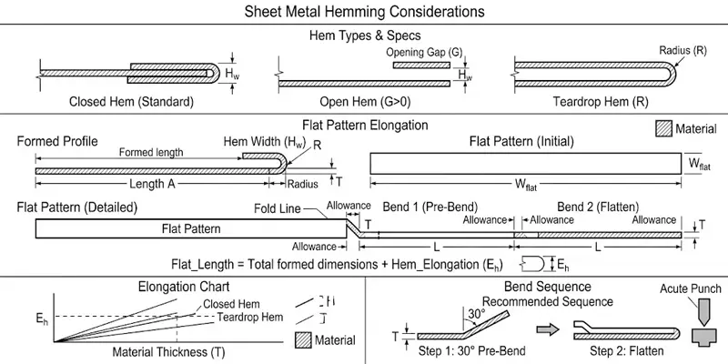
Hemmed parts are won or lost at the drawing stage. Four rules settle most of it:
Call out the hem type explicitly. “Hem” is not a specification. The drawing should state closed, open, or teardrop — plus the target gap for an open hem or the loop size for a teardrop — because the closing force, the crack risk, and the tooling all follow from that choice. An unspecified clearance is how assembly dimensions drift.
Budget the elongation in the flat pattern. A closed hem stretches the material by roughly 43 percent of the thickness under perfect conditions — Benson’s worked example on a 0.074 in. 14-gauge part puts the hem elongation at about 0.031 in. The key word is perfect: hit the hem harder and the elongation grows; hit it softer and it shrinks. The working rule is to use 43 percent as the starting allowance, then bend a test piece and build real numbers for the materials the shop hems regularly. The bend lines around the hem — including the inner and outer 90° bends that cross the doubled thickness — follow the standard bend-deduction arithmetic, with the hem allowance split half on each side of its bend line.
Decide the bend sequence across a doubled edge. There are two ways to form a part that bends across a hem: close the hem first and make the 90° bend over two material thicknesses, treating the double layer as a single blank; or form both 90° bends separately and close the hem last. The first is cleaner when the die width produces the right radius through the doubled thickness; the second is the fallback, and Benson’s advice for it is to cut a few extra setup pieces for the first run.
Respect the general DFM conventions. Standard design guidance for sheet metal — such as Protolabs’ design-for-fabrication whitepaper — keeps features away from bend lines at roughly four times the material thickness (4T) and favors a uniform bend radius across a part to minimize setups. Hems interact with these conventions: a hem eats flange length, and a hemmed edge near a cutout or another bend line concentrates exactly the stretching the 4T rule exists to avoid.
Selecting a Press Brake for Production Hemming
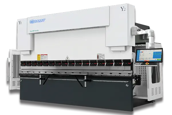
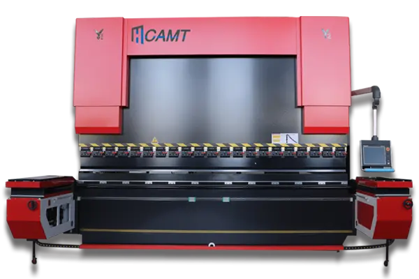
If hemming is a regular part of your production, machine selection should start from actual component drawings rather than nominal tonnage alone. A CNC press brake handles hemming and flattening well when the machine, tooling, and clamping arrangement are properly configured — but CNC control alone does not guarantee a successful hem.
| Machine factor | Why it matters |
|---|---|
| Rated bending force | Must accommodate the actual flattening load, not just the air-bending load |
| Frame rigidity | Helps maintain stable tool alignment under closing loads |
| Ram and bed parallelism | Influences consistent closure along the bend |
| Stroke and open height | Must accommodate the tooling and workpiece in both stages |
| Tool clamping system | Must securely hold the punch through an off-center, thrust-loaded hit |
| CNC control | Supports repeatable positioning, stroke steps, and pressure settings |
| Workpiece support | Controls handling and distortion on large panels |
Before requesting a quotation, prepare:
- Material grade and thickness.
- Maximum hemming length.
- Required hem type: closed, open, or teardrop.
- Initial flange dimensions and required bend radius.
- Expected daily or monthly production volume.
- Required finished-edge tolerance.
- Existing punch and die specifications, if available.
For complex components, provide a 2D drawing or 3D CAD file so the forming sequence can be reviewed for tooling interference before the order is placed. Depending on your existing equipment, sensible upgrades may include CNC system improvements, a clamping retrofit for faster, more repeatable tool changes, crowning systems, and operator training — CAMT’s technical support and training programs cover machine operation, tooling setup, and bending process optimization.
Practical Tips for Consistent Hems
- Standardize the pre-bend. Use the same validated pre-bend geometry for every batch of a given part; avoid re-deriving it visually each run.
- Verify material thickness at setup. Small thickness variations move the final gap, especially on tight-tolerance assemblies.
- Run a controlled first-piece inspection. Closure, straightness, surface, and dimensions — measured, not eyeballed, before the run is released.
- Keep the tooling clean. Particles and debris between the sheet and the closing surface cause both marks and uneven pressure.
- Record validated parameters. Material grade, thickness, tooling configuration, pre-bend angle, final stroke position, and inspection results — the record is what makes the next setup fast.
- Train operators on the two stages. They should know the difference between pre-bending and flattening, recognize the defects above, and know when to stop on abnormal noise, deformation, or tool movement.
Frequently Asked Questions
What is the difference between hemming and flattening?
Hemming is the complete two-stage process of folding an edge back on itself and closing it to a defined profile. Flattening is the single closing action — and a flattening toolset is also used to straighten material, like a heavy hammer. A specialized hemming tool stops at the intended profile; a flattening die kept on the stroke can crush the hem fully flat.
What angle should I use for the pre-bend?
Most shops pre-bend to roughly 30°, working anywhere in the 30° to 45° band depending on the hem profile, material, and tooling. Consistency along the part matters more than the exact number — and the inside radius formed on the acute hit should match the finished hem radius. Validate the angle on the actual production material before committing.
Why does a hem crack during flattening?
Cracking at the fold almost always traces to the material’s ductility meeting too aggressive a geometry: a hard temper such as 6061-T6, an inside radius tighter than the alloy tolerates, or a closed profile on material that should be a teardrop. Check the pre-bend radius and grain direction first; then redesign the profile rather than adding force.
Does hemming require more tonnage than air bending?
Yes — often substantially more, because the closing hit compresses the material against a surface rather than forming it through three-point contact. Air-bending tonnage formulas do not transfer: calculate the closing force for the actual hem geometry and verify it against the machine rating and the tooling’s load limits before the first hit. Hems thicker than roughly 3 mm frequently need custom tooling.
What is the difference between a closed hem and an open hem?
A closed hem presses the folded edge flush against the parent sheet — the strongest, most compact edge, but the highest force and crack risk. An open hem retains a specified gap: lower closing stress, friendlier to crack-sensitive and coated materials, and useful for interlocking assembly. The choice belongs in the drawing, not at the brake.
Can a standard press brake handle hemming?
Yes, provided it has the force capacity, stroke, and open height for both stages, plus suitable acute and closing tooling and a clamping system that holds the punch through a thrust-loaded hit. The machine’s nominal tonnage alone does not establish suitability — the flattening force for the specific tooling and hem geometry does. If that number is uncertain, request an engineering assessment before production.
Conclusion
Hemming and flattening reward the shops that plan them: a profile chosen for the material rather than against it, a tooling setup matched to hem length and volume, a flat pattern built on tested elongation numbers, a closing stroke verified against the load path, and an inspection that measures instead of guesses. A drawing that arrives at the brake with those decisions already made turns what is so often the department’s bottleneck into just another bend — and opens up part designs that fasteners and welds can’t match.
If you are introducing hemming into your production line, or getting inconsistent results from your current equipment, CAMT can help evaluate the press brake configuration, tooling arrangement, and process requirements for your application. Browse the full press brake line to compare machine configurations, or contact us directly with your material specifications and part drawings — we’ll review the bending plan with you.