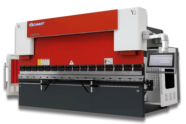
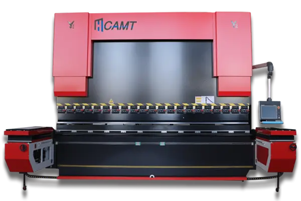
Thick plate does not fail a press brake the way thin sheet does. A 2 mm panel that runs out of tonnage simply stops. A 20 mm plate that runs out of tonnage makes the machine labour, heats one cylinder, flattens a die shoulder, or comes off with 88° at both ends and 93° in the middle — all while the nameplate still says there is capacity to spare. The gap between the number on the plate and the work the plate has to do is what this guide is about.
The short version, before the arithmetic:
- Force rises with thickness squared and falls as the die opening widens. A 20 mm bend at 8 × t costs about 163 tonnes per metre; the same bend at 12 × t costs about 109. The die you pick moves the tonnage further than the grade does.
- 8 × t is a mild-steel habit, not a rule. For wear plate the steel mill’s own guide asks for 12 to 16 × t and a punch radius of 3 to 5 × t.
- Capacity per metre, not total tonnage, decides how much plate forms in one stroke. A 600 t machine on a 7 m bed is worth 86 t per metre across the full length — 10.5 mm mild steel end to end, or 3.7 m of 20 mm.
- Tooling, clamping and die shoulders set a lower ceiling than the machine does on short, concentrated bends.
- Past roughly 8 m, or where one bend needs the tonnage of two machines, tandem is the answer — provided tonnage per metre matches on both sides.
Five limits decide whether a thick-plate part is makeable: tonnage per metre, tooling load, ram and bed deflection, the frame envelope, and the weight of the part itself. Three are fixed when you buy the machine; two are managed with tooling and handling. That is why what follows runs tonnage first, dies second, machine third.

Tonnage per Metre, Not Tonnage on the Nameplate
The industry formula for air bending is a three-point bending calculation written in shop shorthand:
P (kN) ≈ 1.42 × σb (MPa) × t² (mm) × L (mm) / (1000 × V (mm))
where σb is tensile strength, t is thickness, L is bend length and V is die opening. The constant 1.42 reproduces the familiar “650 × t² × L / V” shortcut for 450 MPa steel, so the two agree by construction rather than by luck. For the derivation, worked examples and the chart for other grades, see our guide to the press brake tonnage formula. What matters here is the shape of the equation.
| Plate thickness | V at 8 × t | Tonnes per metre | V at 12 × t | Tonnes per metre |
|---|---|---|---|---|
| 6 mm | 48 mm | 49 | 72 mm | 33 |
| 8 mm | 64 mm | 65 | 96 mm | 43 |
| 10 mm | 80 mm | 81 | 120 mm | 54 |
| 12 mm | 96 mm | 98 | 144 mm | 65 |
| 16 mm | 128 mm | 130 | 192 mm | 87 |
| 20 mm | 160 mm | 163 | 240 mm | 109 |
| 25 mm | 200 mm | 204 | 300 mm | 136 |
| 30 mm | 240 mm | 244 | 360 mm | 163 |
| 40 mm | 320 mm | 326 | 480 mm | 217 |
Figures are 90° air bending of mild steel at 450 MPa. Stainless, wear plate and high-strength structural grades scale roughly with tensile strength, so 1,400 MPa wear plate needs about three times the tonnage at the same die opening. Note what the paired columns do: at a given thickness, widening the die from 8 × t to 12 × t removes a third of the force. At a given die, thickness dominates everything. That is the distinction worth carrying into a quotation: hold the die and doubling the thickness quadruples the force, scale the die with the thickness as the 8 × t habit does and it merely doubles. The two cases get quoted interchangeably and they are not the same purchase.
Now convert that into what a machine actually delivers — same assumptions, applied to the published bed length of each model. Total tonnage divided by bed length is not a limit anyone publishes, but it is the number that decides whether a full-length part forms in one stroke:
| Model | Nominal force | Bending length | Tonnes per metre, full bed | Thickest mild steel, full length | 20 mm plate per stroke (8 × t) | 20 mm plate per stroke (12 × t) |
|---|---|---|---|---|---|---|
| 200 t / 3200 | 200 t | 3.2 m | 62 | 7.7 mm | 1.2 m | 1.8 m |
| 250 t / 4000 | 250 t | 4.0 m | 62 | 7.7 mm | 1.5 m | 2.3 m |
| 300 t / 5000 | 300 t | 5.0 m | 60 | 7.4 mm | 1.8 m | 2.8 m |
| 400 t / 6000 | 400 t | 6.0 m | 67 | 8.2 mm | 2.5 m | 3.7 m |
| 500 t / 6000 | 500 t | 6.0 m | 83 | 10.2 mm | 3.1 m | 4.6 m |
| 600 t / 7000 | 600 t | 7.0 m | 86 | 10.5 mm | 3.7 m | 5.5 m |
Read the fourth column and the pattern is uncomfortable: it barely moves. Going from a 200 t / 3.2 m machine to a 600 t / 7 m machine triples the tonnage and more than doubles the bed, and buys under 3 mm of full-length thickness. What it really buys is length at a given thickness — exactly what a structural shop needs, and exactly what a buyer fixated on tonnage does not realise they are paying for.
The last two columns are the ones to quote from. On the 600 t / 7 m machine, 20 mm mild steel runs at 163 t per metre, so one stroke forms 3.7 m. The same plate on a 240 mm die needs 109 t per metre and forms 5.5 m — half again as much work from the same machine, bought with a die change rather than capital. Against that, the inside radius moves out to roughly 38 mm and the minimum flange to about 156 mm, which the drawing may not allow. That is a drawing decision before it is a machine decision.
One cross-check, since it is the kind of coincidence worth distrusting: the 600 t model’s published maximum of 10–12 mm for mild steel lands in the same range as the full-length column above. Neither number limits what the machine will bend; both limit what it will bend across the whole bed.
Die Opening: 8 × t Is a Starting Point, Not a Rule
The 8 × t convention exists for a reason. A die that is too narrow puts the two support points close together, shortens the lever arm and drives force up steeply; it also crushes the inside radius toward a crease and needs a short flange to work at all. A die that is too wide lowers the force, opens the radius, lengthens the minimum flange and increases springback.
For thick plate the interesting question is which way to move, and the answer depends on the grade rather than the thickness.
| Plate | Die opening | Inside radius (approx.) | Minimum flange (approx.) | Tonnes per metre, mild steel |
|---|---|---|---|---|
| 10 mm | 80 mm (8 × t) | 13 mm | 52 mm | 81 |
| 16 mm | 128 mm (8 × t) | 20 mm | 83 mm | 130 |
| 20 mm | 160 mm (8 × t) | 26 mm | 104 mm | 163 |
| 20 mm | 240 mm (12 × t) | 38 mm | 156 mm | 109 |
| 25 mm | 200 mm (8 × t) | 32 mm | 130 mm | 204 |
| 25 mm | 300 mm (12 × t) | 48 mm | 195 mm | 136 |
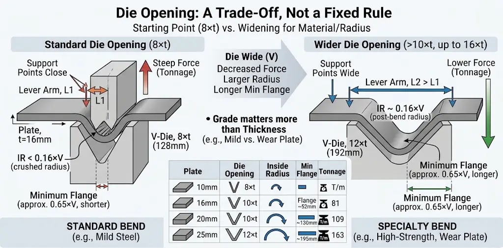
For mild and low-alloy structural plate, 8 × t is a reasonable start and 10 × t is often the better compromise past 16 mm, because it relieves die shoulder pressure without pushing the radius where the drawing cannot follow. Our guide to choosing a V-die opening covers the geometry and the flange interaction.
For wear plate and other high-strength grades, mill guidance is much wider than shop habit. SSAB’s bending guide for Hardox wear plate specifies a minimum die opening of 12 × t below 8 mm, 14 × t from 8 mm to 20 mm, and 16 × t at 20 mm and above, with a minimum punch radius of 3 to 5 × t depending on grade and on whether the bend line runs across or along the rolling direction. A 20 mm wear plate therefore wants a 320 mm die and a punch radius of 90 mm or more — a different tooling world from the 160 mm die the 8 × t habit suggests.
Two consequences follow, and both land on the drawing. A wider die means a larger inside radius, and a larger radius means a longer minimum flange, roughly 0.6 to 0.7 × V for a standard 90° air bend. If your minimum flange length is fixed by the part, the die is fixed and the tonnage follows. If the drawing allows a radius change, check it against minimum bend radius by material before assuming the wider die is free.
Radius and springback are one decision, not two. The figure of roughly 0.16 × V is the radius you get after the load is released, not the radius under load; the material always springs part of the bend back out. That gives two corrections with two different mechanisms: a short angle is fixed by driving the ram deeper, and a radius that is too large cannot be fixed by pressure at all. You either change the die or change the process. This is why a drawing that calls for a tight inside radius on 20 mm plate drives the die choice, the tonnage and the machine size, in that order — and why operators who try to “press the radius in” finish the shift with a mushroomed punch and the same radius.
Why Thick-Plate Estimates Run Light
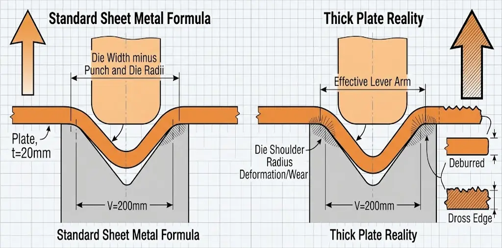
Simple tonnage charts are built around sheet, where punch and die radii are small compared with the die opening. At 20 mm and above that assumption collapses, and two published details explain most of the discrepancy.
The first is the lever arm. The mill’s bending formula for its own plate divides by the die width minus the die entry radius minus the punch radius — not by the die width alone. On 20 mm wear plate running a 320 mm die, a 10 mm die entry radius and a 90 mm punch, that is 220 mm of effective lever instead of 320 mm, and the calculated force rises from about 179 t per metre to about 260. On 1 mm sheet the same correction moves the answer by a fraction of a percent. Nothing about the arithmetic changed; the geometry did.
The second is the tooling condition itself. The same guide asks for a die edge radius of at least half the plate thickness — 10 mm or more on 20 mm plate — and for die edges as hard as or harder than the plate being bent. A die that was fine on 6 mm will mark, flatten and eventually deform on 20 mm wear plate, and once the shoulder radius has flattened, the effective die opening has changed and so has the bend.
Both effects push the same way: an estimate built from a sheet-metal chart, or from a formula that ignores tool radii, is a floor for thick plate, not a ceiling. Two habits close the gap. Put the radii into the calculation, or ask the tooling supplier for the rated tons per metre of the specific punch and die you intend to run. Then leave a buffer — as the specialists interviewed for this account of large-workpiece bending put it, needing 30 tons per foot from tools rated at 32 is not a good idea, because material a little harder than specified puts you outside the rating.
There is a third, quieter factor: the cut edge. Thermal-cut and sheared edges should be deburred and radiused before bending, partly because a hard, ragged edge is where cracks start, and partly because a proud dross bead on the bottom face concentrates load on the die shoulder. On 20 mm plate that is ten minutes with a grinder against a scrapped part.
Punch Radius, Tooling Load and Clamping
Machine tonnage is a total. Tooling load is a rate, and a rate applied to a short length. Those two statements are the whole of this section, and they are why a 600 t machine can still destroy a die.
A 300 mm long bend in 25 mm plate needs 204 t per metre, which is 61 t over that section. That is comfortably inside the machine’s rating and may be well outside the tool’s, because the load is concentrated on 300 mm of a punch and die rated per metre across their full length. The full chain — machine, ram, clamp, holder, punch, die — is covered in our article on tooling load limits in tons per metre, and it is worth reading before any thick-plate job goes on a machine you did not size for it.
Nose radius is where cracks are decided. A sharp punch concentrates strain on the inside face of the bend, which is the same event as an outside crack on a thick plate, seen from the other side. That is why the mill’s 3 to 5 × t figure exists, and why “increase the pressure” is the wrong reply to a crack: the defect is upstream of the pressure setting.
A punch has a rating of its own. Check the rated load per metre, material and hardness, cross-section, and the holder it sits in. A punch that fits the holder is not thereby suitable: thick-plate work mushrooms tips and spreads shanks, and both failures begin as a bend that drifts a degree over a shift.

Clamping has to hold under load, not just under gravity. At high tonnage the punch wants to walk in the holder. Hydraulic upper clamping and a holder that grips the shank properly are not luxuries at this scale — a punch that shifts a few tenths during the stroke produces a bend that no amount of angle correction will fix consistently. Our tooling clamping systems cover that interface.
Big tools are heavy tools. A 3 m punch for 20 mm work is not a one-person lift, and swapping it takes time a quotation rarely accounts for. Segmented tooling and die carts pay for themselves on changeover alone, and tools that change tip radius let you keep one punch body and vary the radius instead of the whole set. Our tooling and tool storage service covers the handling side.
Variable-width V dies are tempting and conditional. A CNC-controlled variable die changes opening in minutes instead of hours, a genuine gain when a shop bends 12, 16 and 20 mm on the same machine. The limitation is geometric: the shoulders ride on a wide block with tracks, so tall negative flanges become impossible to form because you often cannot bend downwards. Check the part before committing to the tool.
One process note that belongs with the tooling: above roughly 20 mm, strain rate and local temperature rise start to matter on high-strength plate, and the mill’s guidance is to bring punch speed down rather than push tonnage up. A slower stroke also gives the operator a chance to stop a bend that is going wrong, which on a 452 kg part is worth more than the cycle time it costs.
Deflection, Crowning and the Bend That Bows
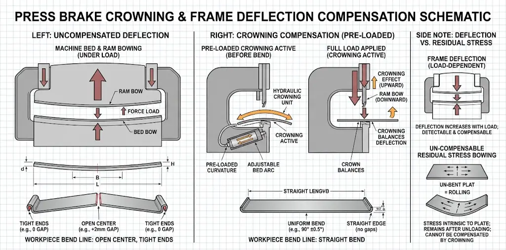
Every press brake deflects under load. The ram and bed bow apart in the middle, the centre of the bend receives less penetration than the ends, and the result is a part that is tight at both ends and open in the centre. Crowning compensates for exactly that: the bed or ram is pre-loaded in the middle so the assembly straightens out under working load.
Two things about crowning matter more on thick plate than on sheet. The load is high, so the deflection is large and the correction is not a trim. And the correction has to follow the job — as the account of large-workpiece bending notes, an accurate automatic crowning system should take the job data and calculate how much crowning is needed, and on a tandem it is not optional, because four or six cylinders now have to hold one straight line together. Our crowning system page describes how the compensation is applied across the bed.
Crowning also assumes the frame holds still. If the side frames twist or the ram is not parallel, the correction is chasing a moving target and no amount of table adjustment will converge. That is why frame stiffness, cylinder arrangement and Y1/Y2 position feedback belong in the same conversation as tonnage: finite element analysis at design stage is how a builder finds the stress concentrations and the frame deflection before a customer finds them in a part.
There is a second defect crowning cannot touch, and confusing the two wastes a lot of trial bends. If the profile curves along the bend line — the part bows in plan rather than opening in the middle — that comes from residual stress through the thickness, and its magnitude depends mainly on flange height and profile stiffness. The mill’s guide is explicit that a bend profile curved along the bend line cannot be compensated by crowning. The fixes are on the part and the process: flange proportions, bend sequence, stress relief, sometimes a different rolling direction. No amount of bed shimming will straighten it.
Frame, Daylight and Handling: The Limits Nobody Quotes

Three machine dimensions decide whether a thick-plate part is makeable at all, and none of them appears in a tonnage discussion.
Distance between uprights limits any part that has to pass through the frame rather than sit on the bed. A formed box or a stiffened channel is limited by the gap between the side frames, not by the bending length. On our heavy-duty range that gap runs from 2,700 mm on the 200 t model to 7,000 mm on the 600 t / 7 m model, against nominal bending lengths of 3,200 to 7,000 mm — the two numbers are not interchangeable.
Throat depth sets how far a return flange can reach back over the bed, and it is the dimension that ends the conversation on deep sections. Thick plate makes it worse, because the flange is stiff and cannot be persuaded.
Open height and stroke have to accommodate a tall tool stack plus the part. Thick-plate tooling is physically bigger, and a deep box on top of it can exceed the daylight of a machine with ample tonnage. Our guide to choosing bending length, throat depth and opening height works through the arithmetic, including the working space above the blank.
Then there is handling, which is where thick plate quietly loses its margin. A square metre of 20 mm steel weighs 157 kg, so a 2.4 × 1.2 m blank is 452 kg and needs a crane or a vacuum/magnetic lifter, and it needs somewhere to land. Follower supports carry the weight of the blank as the bend forms, which keeps hands off the part and keeps the flange from dragging the bend out of angle; that is what our bending follower supports are for. Without them, a two-person team fighting a heavy plate will produce a different angle on the last bend of the shift than on the first, and the machine will get blamed for it.
Matching Thickness and Length to a Machine
With tonnage per metre, die choice and the frame envelope in hand, selection becomes fairly mechanical. The table is a starting point for mild and low-alloy structural plate, not a specification — grade, die and part geometry still decide.
| Work pattern | Typical requirement | Machine class to look at |
|---|---|---|
| 6–10 mm, up to 3 m, mixed batch | 49–81 t/m | Synchronised 3–4 axis machine, 100–200 t |
| 8–12 mm, 4–6 m, structural sections | 65–98 t/m | Heavy-duty frame, 300–400 t, crowning, 6-axis control |
| 12–20 mm, short to medium lengths | 98–163 t/m | Heavy-duty 500–600 t, large die openings, hydraulic clamping |
| 16–25 mm over 4 m, or any part past 8 m | 130–204 t/m | Tandem pair, 2 × 200 t to 2 × 600 t, 8–16 m combined |
| Wear plate 400 HB and above | 2.8–3.7 × mild steel at the same die | Heavy-duty plus hardened tooling, 14–16 × t die, reduced ram speed |
| 30 mm and above, routine | 244 t/m and up | Top of this series, short lengths only; past that, size the job as a project |
A tandem is the right answer in two situations, and they are worth separating. The obvious one is length: two 6 m machines coupled give 12 m of bend in one pass, so a ship panel or a girder comes off complete instead of spliced. The less obvious one is tonnage: two 300 t machines give 600 t across the joint, but only for a part that spans both machines at full length. A short, heavy part sitting on one machine gets that machine’s tonnage and nothing more. Our tandem press brake page lists the configurations, and the decision criteria are set out in when you actually need a tandem.
One condition is not negotiable. Tonnage per foot must be identical across both machines, and the same side-loading rules apply as on a single brake — a part that always loads the right-hand machine while only reaching a metre onto the left one will wear that cylinder out early. If the two halves differ in bed length or capacity, the pair is a compromise, not a tandem.
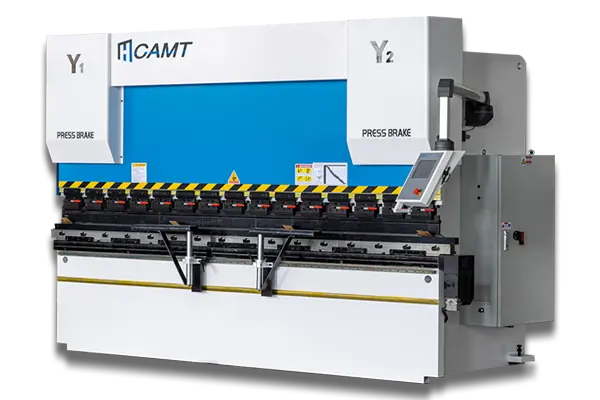
For the single-machine case, the heavy-duty super series runs 200 t to 600 t with beds from 3.2 m to 7 m, multi-point mechanical crowning, and the options that matter here: adjustable large V dies, follower supports, light curtains and tandem coupling.
Symptoms, Causes and What to Check First
Most thick-plate failures look alike at the machine and are entirely different underneath. Work down this table before changing a setting.
| Symptom | Usually | Check first |
|---|---|---|
| Bend comes up short at both ends and in the middle | Not enough force for the loaded length, or ram depth wrong | Tonnes per metre × loaded length against machine rating; die too narrow for the grade |
| Ends tight, middle open | Ram and bed deflection, or crowning not set for this load | Crowning value against the job, bed and ram condition, Y1/Y2 feedback |
| Part bows in plan along the bend line | Residual stress through thickness — not deflection | Flange height, bend sequence; do not chase it with crowning |
| Inside radius larger than the drawing | Die too wide for the radius wanted | V against the 0.16 × V estimate; consider bottoming or a different process |
| Crack on the outside of the bend | Punch radius, cut edge, or rolling direction | Punch radius against 3–5 × t, edge preparation, plate orientation |
| Die shoulder polished flat, punch tip mushroomed | Concentrated overload on a short bend | Required t/m over the contact length against tool rating |
Safety on Thick Plate
Thick plate raises the consequence of every mistake, and four of them are worth stating plainly.
Nobody stands in front of the ram when high-strength plate is being bent. That is not a stylistic preference; it is what the mill’s bending guide tells its own customers, alongside keeping only qualified people near the machine. A bend that releases stored energy, or a punch that fails under overload, throws material forward.
The load path has to be rated, not estimated. A 452 kg blank moving on a crane is a lifting operation, and overhead and gantry cranes must be marked with their rated load and must not be loaded beyond it. Lifting gear, magnets and vacuum lifters need the same discipline as the crane.
Plate edges and large dies are hazards in their own right. Thermal-cut edges are hard, sharp and sometimes ragged; gloves, deburring and a handling plan are cheaper than stitches. A 3 m heavy-duty die section is not a two-person lift either.
Never re-bend a bend that has already cracked in an attempt to correct the angle. The first pass used up much of the material’s remaining ductility; the second one turns a crack into a break. Treat a change in the sound of the machine under load — a relief valve lifting, a pump labouring — as a stop signal rather than a nuisance.
On the machine itself, point-of-operation guarding is a general requirement for any machine that exposes an operator to injury, and light curtains, laser protection and two-hand control are the usual means at the front of a press brake. Our safety arrangements page covers the options.
Thick plate is not difficult to bend; it is difficult to buy for. The machine has to be sized on tonnes per metre across the length you actually form, the die has to come from the grade rather than from habit, and the frame has to let the part in and out. Get those three right and the bend is the easy part. If you are sizing a machine around a specific plate job, send the grade, the thickness and the longest bend through our contact page — we will work the tonnage both ways, at 8 × t and at the mill’s recommended die, and tell you which configuration lands inside the rating with a margin rather than on the edge of it.
The numbers in this article come from the allowances and bend geometry set out in our sheet metal bending guide.