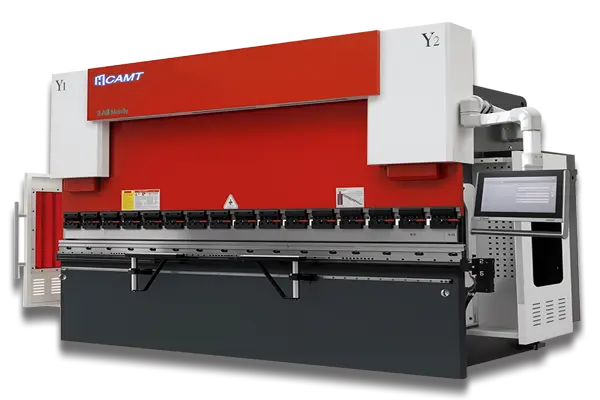
A deep box or electrical enclosure can look correct in CAD but still collide with the press brake tooling during forming. Previously bent walls may strike the punch, holder, clamp, or die before the next bend is complete. Preventing this interference requires three checks: the part’s clearance throughout the bend sequence, the tooling’s working geometry and load capacity, and whether the finished part can be removed safely. This guide explains how to evaluate those factors before production.
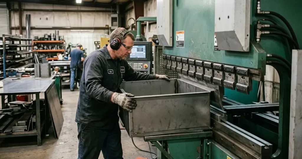
Interference, Clearance, and Collision: Three Different Problems
These three terms are often used interchangeably, but they describe different things, and the distinction shapes how you diagnose a forming problem.
- Interference is the condition. It exists when the workpiece and the tooling or machine occupy the same space at any point in the stroke — a geometric overlap, whether or not the machine actually hits anything yet.
- Clearance is the design and process requirement. It is the minimum space and safety margin you must preserve between the part and the punch, holder, clamp, die, and machine structure at every stage of the bend.
- Collision is the event. It is the specific moment during an actual bend when the part contacts something it should not — on the way down, near the target angle, on the return, or while the part is being loaded or removed.
Keeping these apart matters because a part can have interference on paper, be caught by checking clearance, and never become a collision — or, more dangerously, clear a static check and still collide mid-motion. The goal of this guide is to catch interference early, define the required clearance, and prevent the collision before material is cut.
Why Deep Boxes and Cabinets Collide With Tooling

Interference happens because a flat blank and a formed box occupy very different amounts of space. After the first one or two bends, the workpiece is no longer a sheet; it is a partially closed shape, and every flange that has already been formed reduces the space around the punch, the die, the backgauge fingers, and the machine frame.
A collision can occur at several different stages, and checking only the final position is not enough:
- Loading and positioning. The blank or partially formed part may not seat cleanly against the backgauge without already touching a tool.
- Punch descent. A previously formed wall sweeps up toward the ram or the clamping system before the tip reaches the material.
- Approaching the target angle. The part rotates into the tool body as it nears the final bend angle.
- Return stroke. The punch lifts, and a flange or springback swings the part into a tool on the way up.
- Part removal and rotation. The finished or intermediate shape has no clear path off the tool, or cannot be flipped for the next bend.
Four geometry features create most of these collisions:
- Tall opposing flanges. Two high walls facing each other leave a narrow channel for the tool to enter and retreat.
- Return flanges and back bends. A flange that folds back toward the part creates a pocket that a straight punch cannot clear.
- Narrow four-sided boxes. As the fourth side goes up, the previous three walls wrap around the punch and holder.
- Internal features near bend lines. Tabs, cutouts, or hardware close to a bend reduce the room the tool has to reach the line cleanly.
Depth alone does not decide whether a part can be formed. Box width, flange direction, material, thickness, and the order of operations all matter, and two parts with the same depth can have very different tooling needs.
Diagnosing Interference by Where It Happens
Use this table as a starting point. The “possible direction” column is a first diagnosis step, not a final answer — each case still needs a full geometric and load check against the actual machine.
| Interference symptom | Where to look first | Possible direction to evaluate |
|---|---|---|
| A formed wall hits the straight punch | Punch back profile and the wall's sweep path | Gooseneck punch or another specialized profile |
| The part hits the clamping system | Clamp width, punch height, flange swing path | Compatible clamp-and-tool combination |
| A down-flange hits the die holder or bed | Die height, die holder, space under the part | Taller die, riser, or another forming approach |
| The last side cannot be formed, or the part cannot be removed | Full bend sequence, punch profile, exit path | Re-sequence the operations; consider special tooling or a split design |
| Bends fine, but angle varies along the length | Tool load, machine deflection compensation, material and process | Check load limits and crowning settings |
Takeaway: Locate the stage at which the collision happens — load, descent, approach, return, or removal — before choosing a tooling fix. A static final-position check misses most real interference.
How the Clamping System Changes the Interference Zone
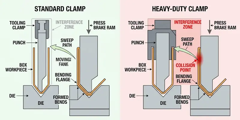
The tool itself is not the only thing that can hit the part. The clamping system behind the punch creates a wider interference zone, and its size depends on the hardware actually installed on the machine.
Do not judge clearance from a tooling-family name alone. American, European, and WILA-style labels describe a tang profile and clamping method, but the real clearance question is what is physically mounted on the press: the specific clamp assembly, its front-to-back width, the punch height it accepts, and the working envelope that combination leaves for the part. Two machines carrying the same tooling-family label can still differ, because clamp generations and retrofits change the geometry.
Heavy-duty clamping systems are physically wider than standard clamps, so they create a much larger sweep path and can collide with a tall flange on a part that would otherwise clear. Before committing a deep box to a specific machine, verify the installed clamping assembly and its front-to-back clearance, not just the tooling standard it is named after. For a fuller comparison of what each tooling standard offers and how they differ at the clamp, see European Style vs. American vs. WILA Tooling: Press Brake Tooling Compatibility Guide.
Choosing the Right Tooling for Deep Boxes and Cabinets
Different interference problems need different tooling. The table below pairs the condition with the tooling direction to evaluate, then each option is covered in the sections that follow.
| Your condition | Tooling to evaluate |
|---|---|
| Formed walls strike a straight punch | Gooseneck punch or another specialized profile |
| Part depth exceeds available punch height | Punch extender, taller punch, or a different forming approach |
| A long down-flange hits the die holder or bed | Taller die, die riser, or die holder |
| Bends of different length, internal cutouts, or hardware on one line | Segmented (sectional) tooling |
| Collision appears only mid-sequence | Re-plan the bend sequence (next section) |
Gooseneck Punches

What it solves. A gooseneck punch has a recessed profile behind the tip, which offsets the punch body away from the part and creates room for a previously formed wall or return flange to pass. It addresses collisions against the punch body or holder — the most common failure in deep box bending — not against the tip doing the work.
How to select it. Check the gooseneck profile against the deepest return flange it must clear, and confirm the working height, rated load capacity, and effective bending length. The profile must also match the machine’s clamping system and the die that will be used under it.
Limitations. A deeper gooseneck gives more clearance but reduces the section of steel carrying the forming load. If the profile is too aggressive for the tonnage and material, the punch can deflect, which shows up as an inconsistent angle across the bend.
Verification. Confirm the formed flange clears the punch at every point in the stroke, and that the punch is rated for the load at the required bending length.
Takeaway: A gooseneck punch buys clearance, but it must be checked for load capacity and compatibility — not just reach.
Punch Extenders and Tall Punches

What it solves. When the part’s depth exceeds the height of available punches, a punch extender combined with a standard punch can recover the lost reach, often at a lower cost than a one-off tall punch. Extenders also have reuse value across jobs.
How to select it. This is a conditional option, not a default. Verify the assembled height of the punch-plus-extender combination, its compatibility with the clamp and the die, its load capacity, and whether the machine has enough stroke and clearance for the taller stack.
Limitations. A height ratio from box depth is only a starting estimate, and it is valid only when its applicability has been confirmed for the specific tooling system and machine configuration. It does not apply to machines with wide heavy-duty clamping systems, which need more clearance than a simple ratio assumes.
Verification. Punch height should be selected from the actual box geometry and the press brake’s available working envelope, not from box depth alone. Check the formed flange positions against the punch body, holder, and clamping system throughout the stroke, and verify that the part can be removed after the final bend.
Takeaway: Extenders recover reach cheaply, but the assembled stack must be re-checked for height, load, stroke, and clearance.
Taller Dies and Die Risers
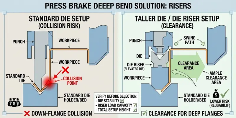
What it solves. Interference is not only an upper-tool problem. A long down-flange — an offset bend or tab far from the edge of the sheet — can collide with the die holder or the machine bed. Taller dies, die risers, or standard die holders raise the die opening higher above the bed so the down-flange has room to swing.
How to select it. Verify that the backgauge can be elevated to the higher top-of-die position, or the clearance gained at the bottom is lost at the gauge. Also confirm the raised die does not conflict with the machine’s open height and stroke, and that there is still enough upper-tool space for the punch to complete the bend.
Limitations. Raising the die consumes open height and changes where the backgauge must sit; on some machines the added height is not available without reducing the material thickness range.
Verification. Confirm the down-flange clears the die holder and bed through the full stroke, and that the backgauge reaches the new die position.
Takeaway: A taller die buys space below the part, but it must not be bought at the cost of backgauge reach or open height.
Segmented Tooling
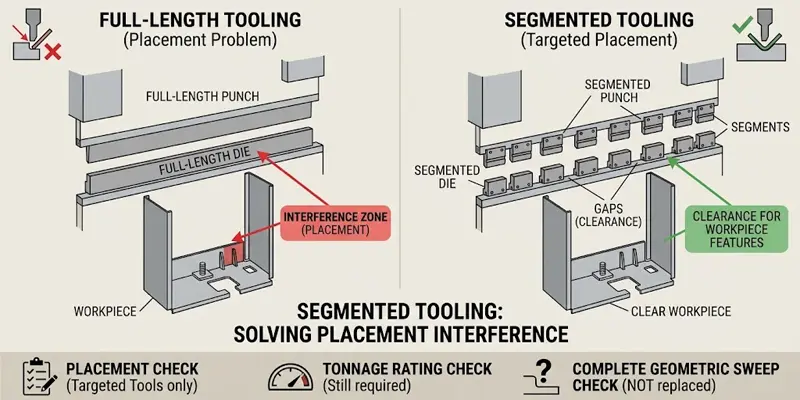
What it solves. For boxes with internal cutouts, hardware, or bends of different lengths on the same line, sectional punches and dies let the operator place tool only where it is needed and leave gaps where a wall or tab must pass.
How to select it. Segment lengths and positions are chosen from the bend line and the features that must pass, so the tool occupies only the working length.
Limitations. Segmented tooling only addresses problems related to tool placement along the bend line. It does not replace a full clearance check for the part’s sweep path, clamp zone, and exit path.
Verification. Confirm the segmented arrangement clears every feature through the sequence, and that the loaded segments are still rated for the required tonnage.
Takeaway: Segmentation solves placement-related interference only; it never substitutes for the complete geometric check.
How to Determine the Right Bend Sequence for Deep Boxes
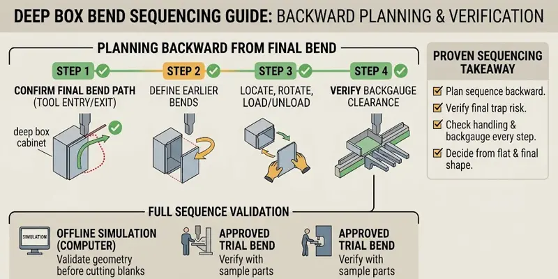
The order in which flanges are formed determines whether the part closes around the tool or stays open long enough to finish. Rather than following a fixed rule of thumb, work the sequence backward from the most constrained bend.
- Confirm the tool’s entry, motion, and exit path for the final bend. The last bend is the one most likely to be trapped, so verify it first.
- Work backward from that last bend to define the preceding operations. Each earlier bend must leave the part in a state that the later bends can still reach.
- Check that the part can be located, rotated, and loaded or unloaded after every bend. If it cannot be handled between steps, the sequence has trapped it.
- Confirm the backgauge does not collide with already-formed flanges as the part changes shape through the sequence.
- Validate the full sequence with offline simulation or an approved trial bend before cutting production blanks.
A wrong sequence does more than cause a collision; it can make the part impossible to load after the first few bends. Sequencing should be decided from the flat pattern and the final shape together, not improvised at the machine.
Takeaway: Plan the sequence backward from the final, most constrained bend, and verify handling and backgauge clearance at every step.
Catching Collisions Before They Happen With Offline Simulation
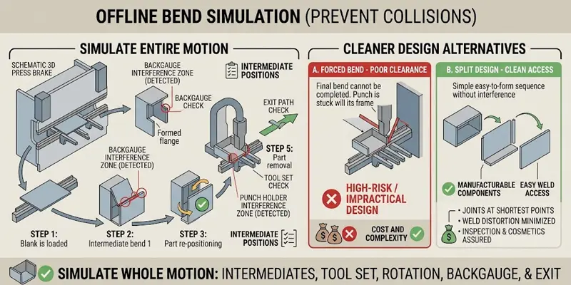
Offline bend simulation is the highest-leverage habit for deep forming. Programming a part offline and simulating the bend sequence exposes collisions and suggests alternatives before any material is cut, without occupying the press brake itself.
When you simulate, check these specific items — not just the final bent shape:
- Intermediate positions throughout every stroke, not only the end position.
- The full tool set and machine structure, including punch, holder, clamp, die, and bed.
- Rotation and re-positioning of the part between bends.
- Backgauge movement against the changing part shape.
- The exit path for part removal after each bend and after the final bend.
For parts where tooling clearance makes a one-piece design impractical, splitting the box into two or more manufacturable components is often the cleaner answer than forcing a marginal bend. The split should be placed at the shortest practical weld or fastening joint, and the decision should weigh weld access, distortion, inspection, and cosmetic requirements rather than clearance alone.
Takeaway: Simulate the whole motion — intermediates, tool set, rotation, backgauge, and exit — not just the final geometry.
What to Check Before You Commit a Deep Box or Cabinet
Before releasing a deep box or cabinet drawing to production, work through this checklist. Treat it as a single-pass engineering review, and record the approved configuration and sequence once it passes.
- Tool geometry. Match the punch profile to the deepest return flange; if a straight punch cannot clear it, a gooseneck or extended tool is required.
- Machine compatibility. Confirm the punch and die fit the installed clamping system and die holder, and that heights work within the machine’s open height and stroke.
- Clearance through the stroke. Verify formed walls clear the punch, holder, clamp, and die at every stage — descent, approach, return — not just the final angle.
- Load limits. Check the tooling is rated for the tonnage at the required bending length.
- Down-flange clearance. Confirm the longest down-flange clears the die holder and bed.
- Backgauge. Verify the backgauge follows the part and does not collide with formed flanges.
- Loading and exit path. Confirm the part can be loaded, rotated, and removed at every step.
- Full-sequence simulation. Run the complete sequence offline and resolve collisions before cutting material.
- Record the approved setup. Document the tooling configuration and bend sequence so the next run does not rediscover the collision.
For enclosures and cabinets specifically, the same interference rules interact with the flatness, squareness, and corner tolerances that electrical work demands. For the recommended press brake specifications and tooling to pair with this kind of work, see Electrical Enclosure & Cabinet Fabrication: Recommended Press Brake Specs and Tooling.
Getting the Machine and Tooling to Work Together
Tooling solves clearance, but it does not replace machine capability. The press brake still needs enough tonnage for the material, bend length, and die opening, plus stable ram repeatability, adequate throat depth, and proper support for large panels. On long enclosure panels, crowning or deflection compensation matters too — a part can pass the collision check and still fail the angle-consistency check if pressure is uneven across the length.
The reliable path is to treat tooling selection and machine selection as one decision. Send the drawing — including material, thickness, flange heights, return flange directions, and batch size — and confirm the tooling plan against the actual machine’s clamp, open height, and stroke before quoting. A material list alone cannot show whether a deep box needs standard punches, gooseneck tools, segmented tooling, or a different sequence.
Review Your Deep Box Bending Application Before Production
A tooling setup that works for one enclosure may not clear the flanges, holder, or machine structure of another. Before releasing a deep box or cabinet drawing to production, verify the tooling geometry, machine compatibility, bend sequence, and part removal path.
For a preliminary tooling review, share your part drawing or flat pattern, material and thickness, flange heights, return-flange geometry, required bend length, and expected production volume. Include the press brake model and tooling standard if available.
These details help determine whether standard punches are sufficient or whether a gooseneck punch, extended tooling, segmented tooling, a revised bend sequence, or a design change should be evaluated.
Tooling decisions rarely stop at one choice. The press brake tooling guide covers the styles, standards and load limits that frame this one.
Frequently Asked Questions
Why does a deep box collide with a press brake punch?
Because after the first few bends the part is no longer flat, and each formed wall reduces the space around the tool. A previously bent side sweeps up toward the punch body or holder before the next bend reaches its angle. The collision usually happens against the punch body, not the tip, which is why a recessed gooseneck profile often clears it.
When should I use a gooseneck punch for box bending?
When a formed flange or return flange would otherwise strike a straight punch or its holder. The gooseneck’s recessed back profile creates room for the wall to pass. Before selecting one, confirm the profile clears the deepest flange, and that the punch is rated for the load at the required bending length.
How do I determine the correct punch height for a deep box?
From the actual box geometry and the press brake’s working envelope, not from depth alone. Check the formed flange positions against the punch body, holder, and clamping system throughout the stroke, and confirm the part can be removed after the final bend. A height ratio is only a rough starting estimate, valid after its applicability is confirmed for the specific tooling and machine.
Can changing the bend sequence eliminate tooling interference?
Sometimes. The order of bends determines whether the part closes around the tool or stays open long enough to finish. Work backward from the final, most constrained bend, and verify the part can be handled and the backgauge cleared at every step. When re-sequencing cannot recover the room, tooling or a design change is needed.
When should a deep enclosure be redesigned instead of using special tooling?
When the geometry leaves no practical tooling or sequence that clears, or when special tooling would cost more than the value of a one-piece design. Splitting the box at the shortest practical weld or fastening joint is often cleaner than forcing a marginal bend. The decision should weigh weld access, distortion, inspection, and cosmetic requirements.