stainless steel is more challenging to bend than many conventional sheet metals. Its higher strength, significant springback, work-hardening behavior, and sensitivity to surface damage can make it difficult to achieve accurate angles and consistent part dimensions on a press brake. A setup that works well for mild steel may produce oversized bend angles, excessive tool marks, or even cracks when used on stainless steel.
Successful stainless steel bending requires more than simply increasing press brake tonnage. You need to understand how the material grade affects forming behavior, select the correct punch and V-die combination, calculate the required bending force, compensate for springback, and protect the material surface throughout the process.

Know Exactly Which Stainless You Are Bending
The most expensive mistake in stainless bending costs nothing at the brake: it is treating “stainless” as a single entry on the quote sheet. Austenitic grades such as 304 and 316 are the most widely used family, but the differences between families show up directly at the machine.
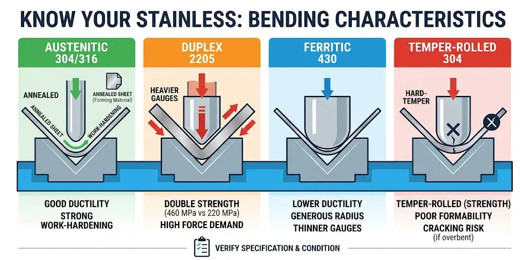
The austenitic grades (304, 316 and their low-carbon variants) are the default for bent sheet parts: good ductility, tough at room temperature, widely available — and strongly work-hardening, which shapes everything else in this guide. Duplex grades carry roughly double the strength of the austenitics — around 460 MPa versus around 220 MPa for the typical austenitic proof stress, as summarised by the Australian Stainless Steel Development Association in its introduction to stainless structural design — and appear mostly in heavier gauges, where their force demand must be planned for. Ferritic grades such as 430 trade ductility for lower cost; they bend, but with a more generous radius and usually in thinner gauges. Cost-driven 201-type austenitics and heat-treatable martensitics like 410 round out the picture, and the rule for both is the same: their properties vary widely by specification and condition, so never carry 304 settings across untested.
Temper matters as much as family. The same 304 chemistry ships either annealed or temper-rolled. Annealed sheet is the forming material. Temper-rolled sheet is chosen for strength after forming, not for formability, and pushing a hard-temper blank through an annealed-sheet setup is one of the classic causes of cracked first articles.
| Family | Common members | What it means at the brake |
|---|---|---|
| Austenitic | 304 / 304L, 316 / 316L | Default bending grades; ductile but strongly work-hardening; expect more force and more springback than mild steel |
| Duplex | 2205 and similar | Around twice the austenitic strength; plan tonnage seriously; mostly heavier gauges |
| Ferritic | 430 and similar | Less ductile; bend with a larger radius; typically thinner gauges |
| 201-type and martensitic | 201, 410 and similar | Properties vary strongly by spec and condition; test before reusing 304 settings |
Why Stainless Behaves Differently Under the Punch
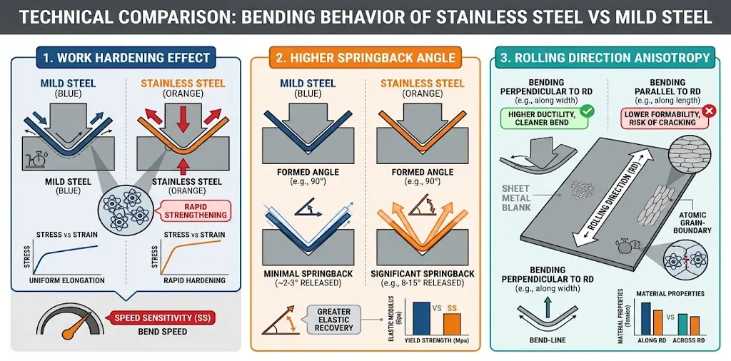
Three material characteristics drive every practical difference between bending stainless and bending mild steel.
Work hardening. Austenitic stainless steels strengthen rapidly as they deform. The British Stainless Steel Association, in its guidance on forming techniques for stainless steel, puts it plainly: austenitic grades show strong work hardening, machinery power levels need to be increased — or existing capability down-rated — compared with carbon steels, and a higher rigidity of tools and machinery is necessary. Work hardening also means the material is at its most formable early in the stroke; BSSA’s advice for flat material is to execute the bend as quickly as possible. In production terms, this is why repeatedly re-bending a wrong angle makes the next correction harder, not easier — fix the program instead of working the metal.
Higher strength, and no sharp yield point. The stress–strain curve of stainless steel is highly non-linear, without the distinct yield point carbon steel shows. That non-linearity is one reason stainless springback is noticeably larger in practice: the elastic recovery you must overbend against is bigger, and it grows with the strength of the particular sheet on your bed.
Direction sensitivity. Stainless steel displays anisotropy — measurably different behaviour parallel and transverse to the rolling direction — and the effect increases with cold work. Rolling direction is not a detail; it is a planning input, and it comes back in the cracking section below.
None of these characteristics makes stainless difficult. They make it less forgiving of defaults.
Tonnage: Size the Force From the Certificate, Not From Folklore
The bending force scales with the material’s tensile strength, with the square of the thickness, and inversely with the die opening. The metric estimating formula most of the industry starts from is:
P (kN) ≈ 1.33 × σb × S² × L / V
where σb is tensile strength in MPa, S is thickness in mm, L is bend length in mm and V is the die opening in mm. The 1.33 coefficient is a common air-bending approximation for 90° work; variants exist, so treat the output as an estimate and confirm near-limit jobs against tooling supplier charts. The full method, including its assumptions, is covered in our press brake tonnage formula guide.
The stainless-specific step is the material factor. In the English-unit method used across The FABRICATOR’s bending columns, Steve Benson’s column on avoiding sharp bends shows the rule directly: divide the material’s tensile strength by the 60,000-psi mild steel baseline. His worked example uses 90,000-psi stainless, giving a factor of 1.5. That is where the shop-floor shorthand “stainless needs about 50 percent more tonnage” comes from — it is not a law of nature, it is the tensile ratio of one specific grade against the baseline. A softer batch needs less; a temper-rolled sheet needs more.
Here is the same logic in metric, isolated so the only variable is the material. A 3.0 mm sheet, 90° air bend, 1 metre of bend, over a 24 mm die:
| Material | Assumed σb | Estimated force | Per metre |
|---|---|---|---|
| Mild steel | 420 MPa | ≈ 209 kN | ≈ 21.4 t/m |
| 304 stainless | 620 MPa (≈ 90 ksi, the grade Benson uses in his example) | ≈ 309 kN | ≈ 31.5 t/m |
Same geometry, same die — the force ratio is exactly the tensile ratio, about 1.48. Two cautions follow. First, these are estimates built on assumed strengths; the actual certificate values for the heat of material you bought are what go into the calculation. Second, the load sits in the tooling under the bend, not spread politely along the bed — so the estimate has to clear not only the machine rating but the load limit of the die set in use. The per-metre logic and its limits are explained in our guide to tooling tonnage per meter.
The stakes are real. Overloading a brake or a die does not announce itself; it bends punches, upsets rams and cracks tooling. Never push a tool or machine close to its rated limit on the strength of an estimate.
Die Opening and Inside Radius: the 20 Percent Rule Applied to Stainless
In air bending, the die opening does most of the geometric thinking. As Cincinnati Incorporated’s bending product manager explains in The FABRICATOR’s article on predictable job flow in the press brake department, for most mild steels, stainless steels and harder aluminums the inside radius forms as a percentage of the die width — change the die, and you change the radius, the bend deduction and the flange dimensions downstream.
For mild steel that natural radius sits around 0.16 of the die opening. For 304 stainless, Benson’s 20 percent rule puts the floated radius at about 20 to 22 percent of the opening, based on 85,000-psi tensile material — and his correspondent’s 90-ksi sheet was actually holding 23 percent. The radius is not something the punch dictates; it is a material-and-die output, and stainless floats a bigger one.
| Parameter | Mild steel (60 ksi baseline) | 304 stainless (85–90 ksi) | Consequence downstream |
|---|---|---|---|
| Material factor for tonnage | 1.0 | ≈ 1.4–1.5 (tensile ratio, grade-dependent) | Higher machine and tool loading |
| Natural inside radius (air bend) | ≈ 0.16 × V | ≈ 0.20–0.22 × V | Bigger radius → different bend deduction → different blank |
| Common V opening starting point | 6–8 × t | Same baseline, often shifted to the wider end | More tonnage relief, larger radius |
| Minimum flange screening value | ≈ 0.6–0.7 × V | Same rule, but V is often larger → flange grows | More blank needed at the bend line |
| Springback handling | Standard overbend | More overbend needed | Die angle and ram depth must allow it |
| Tooling hygiene | Standard practice | Clean, preferably dedicated tooling | Surface and corrosion protection |
The V-opening baseline is still 6 to 8 times thickness — for a 2 mm sheet that is roughly 12–16 mm — with the usual conditions: it depends on the material and the radius the part needs, and it assumes air bending over standard shoulder dies. What stainless changes is where in that range you want to sit, and why. Benson’s worked example is the cleanest illustration: with 0.075-inch sheet on a 0.500-inch die (6.7t), the forming tonnage per inch exceeded the tonnage needed for the punch tip to pierce the surface — the definition of a sharp bend, where the punch nose creases the centre of the radius and amplifies every variation in the material. Widening the die to 0.625 inch (8.3t) dropped the forming tonnage below the piercing tonnage, and the creasing disappeared. For stainless, the wider end of the range is often not a preference but the cure.
The trade-offs run in both directions:
- Wider V = less tonnage and less creasing risk, but a bigger radius. The bend deduction changes and the blank must be recalculated. A die change is never just a die change.
- Bigger V = longer minimum flange. The screening check that a flange must be roughly 0.6–0.7 of the V opening applies to whatever V you chose. The geometry is covered in our minimum flange length guide, and the full die-selection logic in our V-die selection article.
- Punch radius should match or stay under the natural radius. Pick a punch nose as close as possible to the naturally occurring radius without exceeding it, unless the larger radius was planned into the blank from the start. A nose bigger than the floating radius takes over the bend and changes the part.
One more air-bending subtlety matters more for stainless than for mild steel: die angle. The Cincinnati engineers note that air-bend dies should be 70 degrees or less for most work, because the narrower, deeper die space gives the ram room to overbend — and stainless needs that room.
Springback: Overbend, Measure the Released Angle, Verify
Stainless springs back more than mild steel. BSSA’s forming guidance is direct about the fix: a degree of overbending is necessary to counteract the springback of the bend. Form the included angle tighter than the target angle, so that when the elastic recovery releases, the part lands on the angle you actually want.
How much tighter is not a table number. It depends on the strength and temper of the specific sheet, the radius, the thickness and the die — which is why the procedure matters more than any published compensation chart:
- Confirm the material first. A new supplier, batch or temper invalidates the last batch’s compensation; check the certificate before touching the program.
- Bend a sample from the actual production material, then let the punch retract completely before measuring. The angle under load is not the finished angle — only the released angle decides whether the part meets the drawing.
- Measure with a calibrated gauge and record everything: programmed angle, released angle, thickness, grade, punch and die combination, penetration setting. That record is the reference the next batch starts from.
- Adjust penetration in controlled steps and re-test. If a 90° target releases at 93°, the correction lives in the program — and 3° is that setup’s number, nobody else’s.
- Verify repeatability, and on long parts measure at several positions along the bend line, because the middle of a long bend can open while both ends hold target — that is deflection, not springback, and it is handled by crowning, covered below.
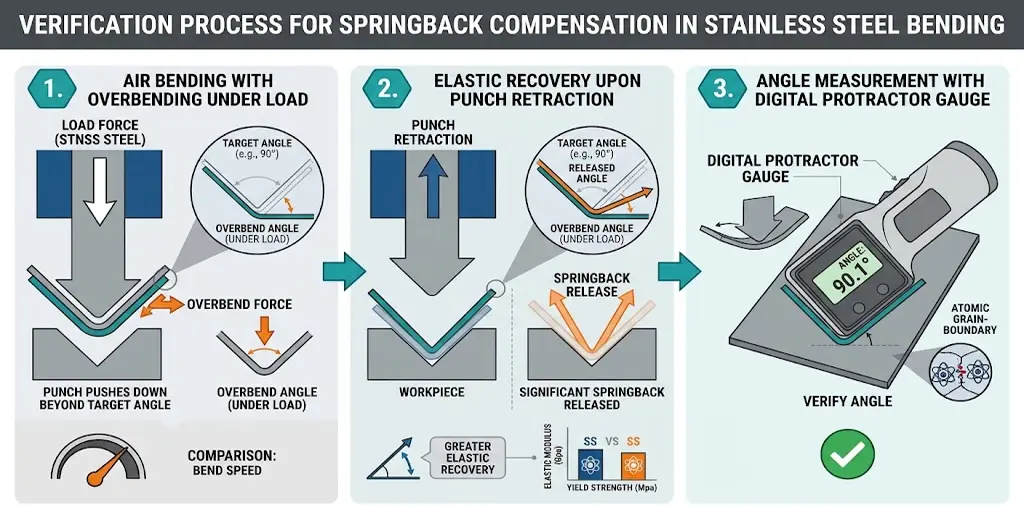
Modern CNC controls can take the feel out of this loop: many advanced press brake controls support programmable springback compensation, and machines fitted with automatic angle measurement can adjust penetration depth in-cycle without releasing the part. The physics and failure modes behind all of this are covered in depth in our guide to springback in sheet metal bending.
Bottoming is sometimes proposed as the springback cure, because the workpiece is pressed against the die geometry and the angle follows the tool. The trade-off is force: bottoming requires substantially higher tonnage than air bending, the exact multiple depending on the material, the tooling and the operation, and it must be checked against the machine rating, the die load limit and the tool manufacturer’s guidance — on the material that is already consuming your largest factor. Coining presses harder still and is rarely justified for general stainless sheet work. For most stainless jobs, air bending with a properly sized die and a disciplined overbend-and-verify loop is the better-balanced answer.
Cracking: Temper, Grain Direction, Edge Condition and the Radius You Ask For
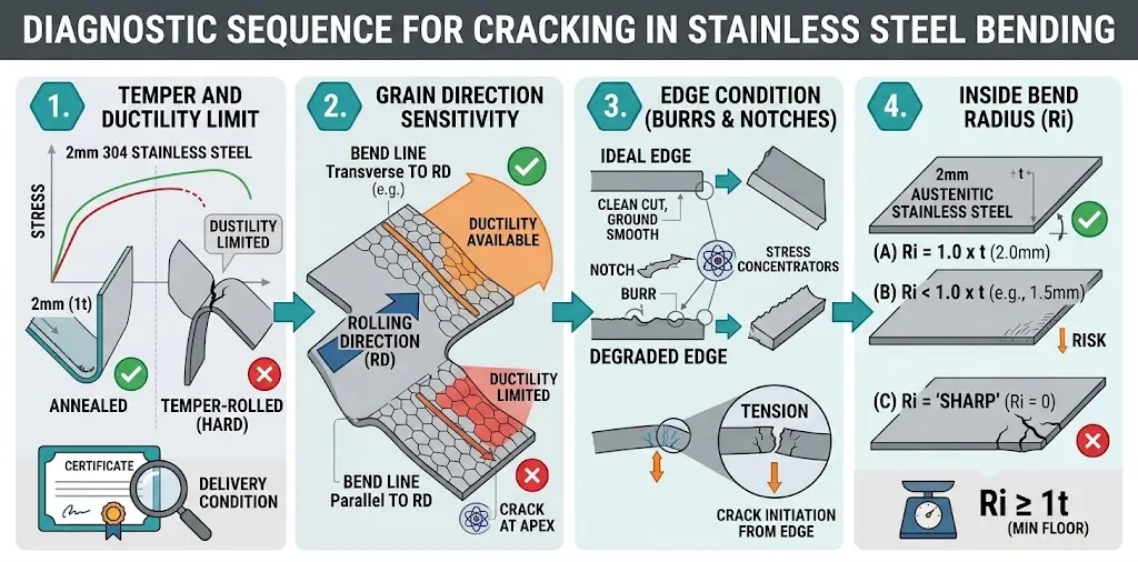
When a stainless bend cracks, the radius on the drawing is rarely the whole story. Work through the suspects in this order.
First suspect: the temper. Annealed is the formable condition. Temper-rolled sheet — and any sheet bought for strength rather than formability — has less ductility in reserve, and a radius that is routine for annealed stock can be beyond it. If cracks appear on material that “should” bend fine, pull the certificate’s delivery condition before the tooling log.
Second suspect: grain direction. Because stainless behaviour differs parallel and transverse to the rolling direction, the orientation of the bend line changes the ductility available at the outside of the bend. Where the drawing allows it, orient bends transverse to the rolling direction and nest parts consistently so the direction is predictable. Where the drawing pins the orientation, run a trial bend on the actual sheet — the size of the effect varies with material and condition, and it is measured, not assumed.
Third suspect: the edge. Burrs and notched cut edges are stress concentrators, and they sit exactly where the outside surface is in tension. Before forming, inspect the cut edges, grind away heavy burrs and keep sharp notches away from bend lines — this matters most on laser-cut cosmetic and structural parts.
Fourth suspect: the radius itself. BSSA’s guidance for flat material is that inside radii sharper than roughly one times the material thickness should not be attempted in the austenitic grades. That is a floor, not a target — confirm the specific requirement against the material supplier’s bendability data for the actual grade and condition.
The full diagnostic sequence for cracks lives in our article on sheet metal cracking at the bend; aluminium has its own behaviour, covered separately in our guide to bending aluminium without cracking.
Protecting the Surface — and the Corrosion Resistance

Stainless parts are usually stainless for a reason: the finished surface matters for hygiene, appearance or corrosion service. Bending is where that surface is most at risk, and the protection is procedural before it is technical. BSSA’s standing advice is that all fabrication on stainless should be carried out in a clean and, if possible, dedicated environment. At the brake, that means:
- Keep carbon steel away from stainless tool contact. Tooling that has been running mild steel carries debris; pressed into a stainless surface under bending load, it can later surface as rust staining that looks like a material failure but is shop-floor transfer. Clean tooling before stainless runs; dedicated tooling for regular stainless work is better still.
- Leave the protective film on where the process allows. BSSA’s forming and fabrication information sheet notes that certain plastic protective coatings applied to sheet products can remain in position during forming and act as an aid to pressing — provided the film is rated for the operation and does not wrinkle or tear mid-bend.
- Match the tooling to the finish. For brushed and polished work, the options run from larger die shoulder radii and polished contact surfaces to urethane inserts and purpose-designed non-marking tooling. Cosmetic failures at the die are diagnosed and prevented in our article on die marks in sheet metal bending.
- Handle like a surface, not a plate. A bright blank dragged across the bed or a gauge is marked before the ram ever comes down.
A surface that survives bending without embedded steel, deep die marks or film damage is also the surface that keeps its corrosion performance in service — which is why hygiene here is a specification, not a nicety.
Machine and Tooling Requirements When Stainless Is Regular Work

Occasional stainless jobs test your setup. Stainless as a product mix tests your machine. The differences are all visible in the force path.
Rigidity and power. BSSA’s guidance doubles down on both: power levels must be higher (or existing capability down-rated) and tool and machine rigidity higher than for carbon steels. A machine that forms mild steel comfortably can be working near its practical limits on the same stainless job — which shows up as angle variation along the bend, not necessarily as an alarm.
Deflection and crowning. Higher force means more deflection in the ram and bed — the classic symptom is a long part that measures on target at both ends but open in the middle. Compensation systems exist precisely for this regime; how they work and when they are needed is laid out on our crowning system page.
Closed-loop angle control. The overbend-and-verify discipline can be automated: machines with in-cycle angle measurement adjust penetration while the part is still under the punch. On stainless, where the correction per part is larger and the material varies more batch to batch, that feedback loop is worth more than it is on mild steel. Our Genius series CNC press brakes occupy this class of machine — multi-axis CNC control with the crowning and angle-measurement options that stainless volume tends to demand.
Tooling that matches the machine. A precise tooling system on a machine pushed to its limits is a mismatch; so is the reverse. Tooling condition, clamping and storage habits are covered on our tooling and tool storage solutions page.
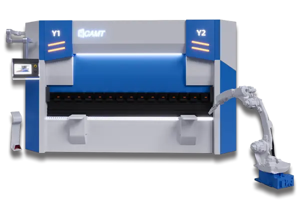
If you are weighing which machine class fits a stainless-heavy mix — tonnage headroom, bed length, control features — the CAMT press brake range breaks the choices down by series.
Troubleshooting Table and the First-Job Checklist
Most stainless defects trace back to one of the decisions above. The table covers the stainless-specific cases; the general press brake fault tree is a subject of its own in our troubleshooting guide.
| Symptom | Most likely cause | First action |
|---|---|---|
| Angle opens more than last batch | New supplier, batch or temper; compensation carried over | Check the certificate, run a fresh test bend |
| Ends on target, middle open | Ram/bed deflection under higher load | Review crowning settings for the stainless load |
| Cracks at a "correct" radius | Temper, rolling direction or edge condition | Pull the certificate; check orientation and burrs |
| Creasing at the bend line | Sharp bend: forming tonnage exceeds piercing tonnage | Widen the V toward 8t; recalculate blank and flange |
| Rust staining at bend points | Carbon steel transfer from shared tooling | Clean or dedicate tooling; re-passivate if required |
And for a first stainless job that is new to your shop, run the sequence in order:
- Pull the certificate — grade, delivery condition, actual tensile strength, thickness and tolerance. No settings before this step.
- Check formability — annealed? Proceed. Temper-rolled or unfamiliar condition? Get the supplier’s minimum bend radius for that condition.
- Plan the bend line orientation — transverse to rolling direction where the drawing allows; note the direction on the traveller either way.
- Calculate the tonnage from the certificate’s tensile strength; check against the machine rating and the die set’s load limit.
- Choose the die deliberately — start from 6–8 × t, shift wider when tonnage or creasing pressure says so, and recalculate blank, radius and flange for the die actually selected.
- Select the punch — nose radius at or just under the natural radius for that die.
- Verify tooling hygiene — clean; dedicated for regular stainless; film retained where the process allows.
- Underbend, correct, record — measure the released angle, correct, and write the final settings against the material heat, then re-check first production pieces and sample the batch periodically.
The numbers in this article come from the allowances and bend geometry set out in our sheet metal bending guide.
FAQ
How much more tonnage does stainless steel need than mild steel?
Enough that the difference must be calculated, not remembered. The honest method is the material factor: divide the tensile strength of your sheet by the 60,000-psi mild steel baseline that tonnage charts assume. A 90,000-psi stainless gives a factor of 1.5; a softer batch gives less, a temper-rolled sheet more. In the metric estimating formula the same effect appears directly as the tensile term — which is why the certificate, not a rule of thumb, should supply the strength value.
Can you bend 304 stainless on a standard press brake?
Yes, if the machine has the tonnage the certificate calculation calls for, tooling rated for that load, and enough structural rigidity to hold the angle along the bend. What you must not do is read the machine’s mild-steel thickness rating as its stainless capacity — the same thickness in 304 needs roughly one and a half times the force of the 60-ksi baseline.
What V opening should I use for 3 mm stainless?
The 6 to 8 times thickness baseline puts you between 18 and 24 mm, with the exact choice depending on the radius the part needs and the material. For stainless, shops often land toward the wider end — it relieves tonnage and pulls the forming force below the threshold where the punch tip creases the bend. Remember the knock-ons: a wider die floats a bigger radius and demands a longer minimum flange, so the blank must be recalculated for the die you actually chose.
Why is my stainless part cracking even though the radius matches the drawing?
Check four things before blaming the tooling: the delivery condition of the sheet (temper-rolled material has far less formability than annealed), the orientation of the bend line relative to the rolling direction, burrs and notches on the cut edge, and whether the radius is at or below the material’s minimum for that grade and condition — for flat austenitic material, bends sharper than roughly one times thickness are not recommended in the first place. The systematic version of this diagnosis is in our cracking-at-the-bend article.
Does stainless steel spring back more than mild steel?
Yes — noticeably, and qualitatively more, driven by its higher strength and its non-linear stress–strain behaviour. The compensation is the same principle at a larger correction: form the included angle tighter than target and let the recovery land on the wanted angle, always judging by the released angle measured after the punch retracts. Machines with programmable springback compensation and in-cycle angle measurement shorten that loop considerably.
Can I bend carbon steel and stainless steel on the same tooling?
You can, but regular stainless work justifies dedicated tooling. The industry guidance is to work stainless in a clean and, where possible, dedicated environment — carbon steel debris on shared tooling can press into the stainless surface and show up later as rust staining, and die condition that mild steel forgives will mark a bright stainless finish. If tooling must be shared, clean it before the stainless run and inspect the shoulders.
Conclusion
Bending stainless steel on a press brake is not a harder version of bending mild steel — it is the same process with less margin and more consequences. The material’s higher strength and steep work hardening raise the force and the springback, the 20 percent rule floats a bigger inside radius over the same die, and the surface turns shop-floor hygiene into a specification. Get the sequence right and stainless bends as predictably as anything else on the floor.
If you are sizing a machine or a tooling package around stainless specifically, send us the four facts that decide everything — material grade, sheet thickness, bending length and the part drawings — and our engineering team will help you work out the required capacity and the bending configuration to match.