Every press brake purchase and every new bending job comes down to one number: how much force does this bend actually take? You can estimate it in seconds from four inputs you already know — material tensile strength, thickness, bend length, and the V-die opening. This guide gives you both formulas, a per-metre tonnage chart for mild steel, three worked examples, and the steps that turn a calculated force into a machine decision. If you only need the number, the press brake tonnage calculator runs the arithmetic for you.
Key points up front:
- Bending force scales with the square of material thickness. Doubling thickness roughly quadruples the force — the single most common reason a machine that handles sheet work stalls on plate.
- Two formulas, two unit systems. The metric form takes tensile strength in MPa directly; the imperial form works in US short tons against a 60,000-psi mild steel baseline. Never mix them.
- A calculated force is not a machine rating. Rated capacity, operating margin, working length, upright spacing, and tooling load limits all bear on the final selection.
- The formulas cover air bending only. Bottoming and coining need substantially more force and must be calculated for the specific job.
- Read the nameplate in kN, not in the “T” label. Model designations such as 110T/3200 carry a rounded tonnage figure; the specification table’s kN value is the precise one.
Press Brake Tonnage: The Short Answer
Required force comes from four values you already have: tensile strength, actual thickness, bend line length, and V-die opening. Take 6 mm mild steel at 450 MPa, bent over 2,000 mm in a 48 mm die — the metric air-bending formula returns about 958 kN, or roughly 98 metric tonnes. That is only the demand side. The machine side is whether its rated force, working length and tooling can absorb that demand with room to spare, and that is where most oversizing and most near-limit operation actually happen.
The Press Brake Tonnage Formula
For preliminary metric calculations, the commonly used air-bending formula is:
F (kN) = (1.42 × Rm × T² × L) ÷ (V × 1,000)
The coefficient is an estimating factor, not a physical constant — published variants use 1.33 as well, and the two differ by several percent. Pick one, stay with it, and treat the output as an engineering estimate rather than a laboratory value.
For shops working in inches and US short tons, the equivalent rule is:
Tons per foot = (575 × t²) ÷ V
with thickness and die opening in inches, giving the force per foot of bend for mild steel near 60,000 psi tensile strength. Steve Benson, who publishes this constant as the reliable alternative to printed tonnage charts, also supplies the material correction used with it: a factor equal to your material’s tensile strength divided by the 60,000-psi baseline — a grade specified at 120,000 psi gets a factor of 2.0. Multiply the tons-per-foot figure by the material factor and by the bend length in feet. The length that counts is the inches actually being formed in the stroke — not the length of the tooling sitting in the machine.
Why Thickness Squared Matters
The most important property of the formula is the squared thickness term. Force does not grow linearly:
A machine that bends 3 mm comfortably is working nine times harder on 6 mm. When sizing a press brake, plan around the thickest material you expect to run regularly, not the one on the bench today.
The Five Factors Behind the Calculation
Two jobs with identical thickness can need very different force. Each factor below changes the number — and each is also a place where estimates quietly go wrong.
1. Material Tensile Strength
Force scales with tensile strength, so the value you plug in matters more than any other judgement in the calculation.
The steel values are published data — MatWeb lists A36 bar between 400 and 550 MPa depending on product form, and annealed AISI 304 at 505 MPa — while the aluminum range reflects typical published values for H32 sheet. Treat them as starting points: the same grade varies by alloy, temper, thickness, and supplier, and cold-worked 304 runs well above the annealed figure. The dependable habit is to take tensile strength from the material certificate or mill test report. The classic purchasing error is calculating with mild steel values and then pointing the same machine at stainless or high-strength plate — the formula absorbs the difference honestly, but only if you feed it the real number.
2. Material Thickness
Thickness enters the formula squared, so tolerance matters. A plate ordered at a nominal thickness sits inside a manufacturing tolerance band, and in demanding applications the actual measured thickness — not the label — belongs in the calculation.
3. Bend Length
Total force scales with the length of bend line being formed in that stroke: double the length, double the force. The input is the bend line, not the full bed and not the length of a segmented die — charging the calculation with tooling length inflates both the tonnage figure and the budget. Note that the reverse case carries its own risk: a short, heavy bend may sit well within the machine’s total capacity while exceeding local load limits, which is checked separately in the machine-selection section below.
4. V-Die Opening
The die opening sits in the denominator, so it directly sets the force: narrow the die and tonnage climbs; widen it and the force drops. For conventional air bending, a common starting point is an opening near eight times the material thickness, with the working range running roughly six to eight times. A wider opening lowers the force but forms a larger inside bend radius — roughly 16% of the opening for standard tooling in mild steel — and demands a longer minimum flange to keep the part stable across the groove. Die selection is therefore a geometry decision first and a tonnage decision second; we walk through the full logic in our guide to choosing a V-die opening.
5. Bending Method
Every formula in this guide is an air-bending formula. There is no universal multiplier for the other two methods — the actual increase depends on the material, die geometry, punch radius, and the angle being produced, which is why published rules of thumb disagree with each other. If your parts require bottoming or coining, calculate the force for those specific conditions and verify it against the machine rating, the tooling load limit, and the ram’s centerline load limit with your supplier.
Press Brake Tonnage Chart (Mild Steel, per Metre)
The chart applies the metric formula to mild steel at 450 MPa with a die opening near eight times thickness. It shows force per metre of bend — multiply by your actual bend length.
Reading it is straightforward: 6 mm mild steel needs about 48.9 metric tons per metre, so a 2-metre bend needs about 97.8 tons — the same result the worked example below reaches step by step. For other materials, apply a preliminary ratio of actual tensile strength to the 450 MPa reference, then confirm against the certificate. These are estimating values for preliminary planning, not machine capacity ratings.
Worked Example: 6 mm Mild Steel, Step by Step
A fabrication workshop needs to air-bend a 6 mm mild steel plate, 450 MPa, over a 2,000 mm bend with a 48 mm V-die (eight times thickness).
Step 1 — Identify the parameters. Rm = 450 MPa, T = 6 mm, L = 2,000 mm, V = 48 mm, air bending.
Step 2 — Apply the formula.
F = (1.42 × 450 × 6² × 2,000) ÷ (48 × 1,000) = 958.5 kN
Step 3 — Convert to metric tons.
958.5 ÷ 9.80665 ≈ 97.7 metric tons
Step 4 — Check it against a real machine. The estimated minimum is about 97.7 tons, but a 100-ton-class machine would run this job with almost nothing in reserve. On the CAMT range, the 110T/3200 is rated 1,100 kN — the job would consume about 87% of rating, leaving roughly 13% margin. The next size, 130T/3200 at 1,300 kN, brings the same job down to about 74% of rating. Which is right depends on the rest of the shop’s workload; the arithmetic makes the trade-off visible instead of guessed.
This step is also where the nameplate deserves a second look. The designation 110T/3200 reads as a nominal 110 tonnes over a 3,200 mm bed, but the “T” is a rounded metric-tonne label — 1,100 kN ÷ 9.81 is closer to 112 tonnes — and the kN figure in the specification table is the precise one. Buyers comparing quotes across regions should also remember the short-ton trap: “110 tons” from a US builder and “110T” from a metric builder are about 10% apart, which is exactly why the kN comparison in the opening section matters.
From Calculation to Machine: Five Checks
The calculation produces a force; the purchase order needs a machine. Five checks sit between the two.
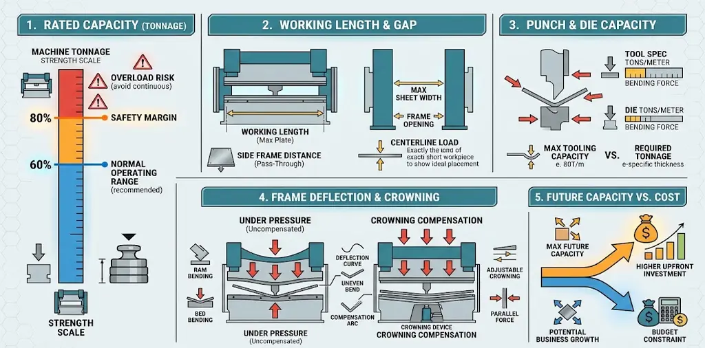
1. Rated capacity with operating margin. Do not select a machine whose rating merely matches the calculated minimum. Material at the top of its thickness tolerance, a batch with higher tensile strength, or a die a few tenths tighter than nominal all push the real requirement upward. Shops that plan typical work well below rated capacity get longer frame and hydraulic life; how much margin is enough depends on the material mix — certified high-strength plate in tight tolerances needs more room than general sheet work.
2. Working length and load position. Tonnage and bed length must be read together: two 200-ton machines with 3,200 mm and 4,100 mm working lengths are not interchangeable for every part. Check the maximum bend length, the distance between uprights, and the permissible load distribution. As a widely used rule of thumb, full machine tonnage should not be applied over less than about 60% of the distance between the side frames, and every machine also has a centerline load limit that only the manufacturer can define — Benson’s advice to operators establishing safe working parameters is to request that figure from the machine builder and to check tooling load limits alongside it. On the 3200-mm models above, the uprights sit 2,700 mm apart, which frames how a short, thick part should be assessed before it goes near full tonnage.

3. Tooling load limits. The machine may have capacity the tooling does not. Punches and dies carry their own allowable load, usually expressed per metre or in kN/m, and the clamping system has limits of its own. The per-metre side of this — what a given tool can safely carry — is a separate calculation, covered in our guide to tooling load limits in tons per metre.
4. Deflection and crowning. Under load, the ram and bed deflect, most visibly on long bends and heavy sections: the angle forms correctly near the ends and opens up in the centre. A crowning system compensates for that deformation and helps hold one angle along the full bend length — a standard evaluation point whenever calculated tonnage, working length, or angle tolerance are on the high side.
5. Future production requirements. A machine sized only for today’s parts is a machine you outgrow. Consider where maximum thickness, material grades, bend lengths, volumes, and automation needs are heading — but resist the opposite error: a higher-tonnage machine is not automatically better, and oversized capacity raises purchase, installation, and operating costs without improving a single part. The objective is capacity matched to realistic requirements, with engineering margin.
Which CAMT Press Brake Configuration Fits
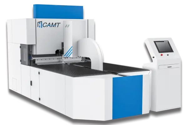
Once the required force is known, the remaining questions are configuration questions. The CAMT press brake range spans rated pressures from 400 kN (40T/1600) to 3,000 kN (300T/3200) and beyond, so most shops can be matched to a machine class directly from the calculation above:
- Standard sheet and plate work — the Economical torsion-bar series covers 2- to 3-axis NC control with servo backgauge, and is the practical starting point when calculated tonnage lands in the mid-range models.
- Multi-bend, precision parts — synchronized and CNC models add axis count and angle control; select tonnage first, then axes.
- Long panels and structural sections — the tandem configuration synchronizes two machines to extend effective bending length, as in the long-bend cases the chart above makes easy to size.
- Thick and high-strength plate — heavy-duty frames with high tonnage and rigid structures, the territory of the 300-ton class in the worked-example range.
- Thin sheet, high cycle rates — servo-electric models bring fast response and no hydraulic oil to the bending drive, provided the tonnage and length requirements genuinely fit.
If you would rather not run the numbers yourself, send our team your material grade, actual thickness, maximum bend length, V-die opening, and bending method — we will calculate the required tonnage for your heaviest parts, check it against the range, and quote a configuration that fits.
Common Tonnage Mistakes at a Glance
This is one screen of a longer buying process. The press brake buying guide runs from part mix and tonnage through to the purchase order.
FAQ
Sources
- Steve Benson, Press brake questions from around the world, The FABRICATOR — imperial tonnage formula, 60,000-psi baseline, material factor as a tensile-strength ratio, bend length defined as inches formed.
- Steve Benson, New to the press brake? Establish best practices in the fab shop from the start, The FABRICATOR — 60%-of-distance-between-uprights rule of thumb, centerline load limit, ram upset.
- MatWeb, ASTM A36 Steel, bar — tensile strength 400–550 MPa (58,000–79,800 psi).
- MatWeb, AISI Type 304 Stainless Steel — tensile strength 505 MPa (73,200 psi), annealed.