Choosing the right V-die opening is essential for achieving accurate bend angles, consistent inside bend radii, and reliable press brake performance. A V-opening that is too narrow can cause excessive tonnage, tool overload, and material cracking, while an opening that is too wide can produce larger bend radii, longer flange requirements, and dimensional inaccuracies. The correct selection depends on material thickness, material properties, bend radius requirements, flange dimensions, and the press brake’s available tonnage. Understanding how these factors interact helps operators select tooling that produces predictable results without unnecessary setup changes or production waste.
What the V-Die Opening Actually Controls
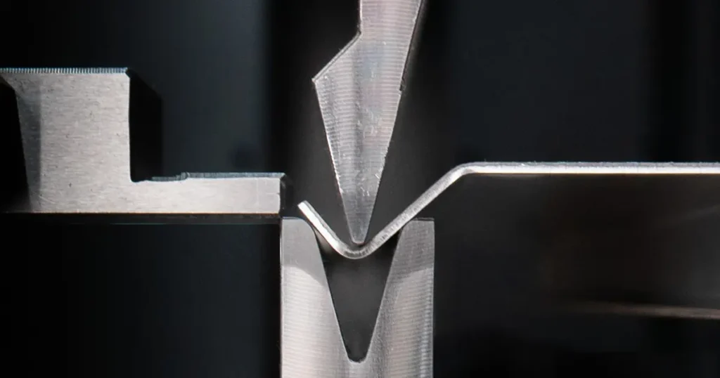
The V-die opening is the distance between the two upper edges of the V-groove in the lower die. During an air bend the sheet rests on those two shoulders and the punch presses it into the gap without touching the bottom of the V, so the opening quietly sets four things at once:
- Forming force. Force scales approximately with the inverse of the die width. A commonly used air-forming formula computes tons per inch as (575 × thickness² ÷ die width) for 60,000-psi tensile steel, corrected by a material factor for other grades. The same relationship works in reverse: a wider opening is the cheapest way to buy tonnage headroom.
- Inside radius. For most mild steels, stainless steels and harder (tempered) aluminums, the inside radius forms as a percentage of the die width — commonly around one-sixth of the opening for air bending standard mild steel. Soft aluminums are the exception: there the punch nose can determine the formed radius.
- Minimum flange. The sheet must span the opening before the bend can form. Widen the die and the flange has to reach further to stay on both shoulders.
- Surface condition. A narrow opening concentrates contact pressure on the die shoulders and the punch nose, which shows up as burnished or embossed lines running parallel to the bend.
Because these four consequences move in opposite directions, every opening choice is a trade-off rather than a lookup:
| Opening choice | Forming force | Inside radius | Flange demand | Springback exposure | Marking risk |
|---|---|---|---|---|---|
| Narrower (toward 6 × t) | Rises sharply | Smaller, closer to the punch radius | Easier to satisfy | Less to compensate | Higher shoulder pressure |
| Balanced (6–8 × t) | Manageable | Near or above material thickness | Conventional | Normal | Normal |
| Wider (toward 10 × t and beyond) | Falls | Larger | Harder to satisfy | Larger — springback increases with die width | Lower |
That last column deserves a second look. Wider openings reduce force and marking, but springback grows with the die width, alongside the yield point and strain hardening of the material. Widening the die trades one correction problem (load) for another (angle recovery), which is why “just open up the die” is not automatically the safe answer.
The Starting Rule: Six to Eight Times Thickness
For air bending on standard-shoulder V-dies, the widely used starting band is an opening of 6–8 × material thickness. Treat it as a starting point, not a specification — the range assumes mild steel, conventional tooling geometry and a free bend that never touches the bottom of the V. (Where that tooling comes from, and how the styles and clamping systems differ, is its own subject — our press brake tooling guide covers the full landscape.)
For quick reference, the band converts to these preliminary openings for conventional mild steel air bending:
| Material thickness | Opening at 6 × t | Opening at 8 × t |
|---|---|---|
| 0.8 mm | 4.8 mm | 6.4 mm |
| 1.0 mm | 6 mm | 8 mm |
| 1.2 mm | 7.2 mm | 9.6 mm |
| 1.5 mm | 9 mm | 12 mm |
| 2.0 mm | 12 mm | 16 mm |
| 2.5 mm | 15 mm | 20 mm |
| 3.0 mm | 18 mm | 24 mm |
| 4.0 mm | 24 mm | 32 mm |
| 5.0 mm | 30 mm | 40 mm |
| 6.0 mm | 36 mm | 48 mm |
| 8.0 mm | 48 mm | 64 mm |
| 10 mm | 60 mm | 80 mm |
| 12 mm | 72 mm | 96 mm |
These are preliminary selection references, not tooling specifications — actual die sizes, material grades and machine capacities must be checked before production.
The floor near 6 × t exists for hard physical reasons:
- Force climbs steeply. Because force scales with the inverse of the opening, moving from an 8 × t die to a 6 × t die on the same part raises the forming load by roughly a third. Below that, the climb accelerates.
- Tooling load rises with it. The punch nose and die shoulders carry the concentrated pressure. Exceeding a die’s rated load per metre is how dies deform permanently — and a damaged V opening then poisons every job that runs through it afterwards.
- Strain and cracking risk rise. A smaller opening wraps the material around a tighter radius, increasing strain on the outside surface of the bend. Brittle materials need wider openings and larger radii for exactly this reason; design references for press brake work put brittle-material dies in the 8–12 × t range, against the usual 5–8 × t for ductile sheet.
The other end has a limit too. Past roughly 10 × t, the radius grows, the flange has to reach further, and the angle recovery you must compensate grows as well. Neither extreme is “wrong” — but both should be chosen deliberately, with the checks in the sections below, rather than inherited from whatever die is nearest the machine.
Why the Bending Method Changes Everything
The multiplier above is an air bending rule. Before you apply it, confirm which process the job actually uses, because the three common methods divide the work differently:
- Air bending forms the angle by penetration depth. Only three points of the tooling touch the sheet — the punch tip and the two die shoulders — and the punch’s depth into the die space sets the final angle after springback. One set of tooling can produce a range of angles, and the die opening, not the punch, largely determines the radius.
- Bottoming presses the sheet against the die angle. The punch tip defines the inside radius and the die angle (plus a small allowance for springback) sets the bend angle. Bottoming typically uses smaller openings relative to thickness and substantially higher forming loads than air bending — which is why bottoming jobs must be calculated and checked against the machine rating, the die rating and the clamping on their own terms, never with air-bending numbers.
- Coining stamps the punch nose into the material. It sits at the extreme end of the load scale, and like bottoming it must be verified separately.
Method also constrains die geometry. As bending engineers at Cincinnati Incorporated put it in a recent review of forming fundamentals, all the air bend formulas work only while the material touches the two shoulders and the punch tip: “for most air bending applications, you need to use dies that are 70 degrees and less.” Once the outside radius of the bend touches the bottom of the V, the legs lift off the shoulders and, practically speaking, the bend becomes unpredictable. So when a selection chart offers you a choice of die angles for the same opening, the shallower-angle die is the one that keeps the air-bending math valid across the whole compensation range.
If your shop mixes methods, label the tooling and the setup sheets accordingly. The most common selection error in mixed shops is not choosing a bad opening — it is choosing a good air-bending opening and then running a bottoming job through it.
How Material Changes the Starting Point
Thickness alone does not select a die. The material adjusts both the force calculation and the angle behaviour:
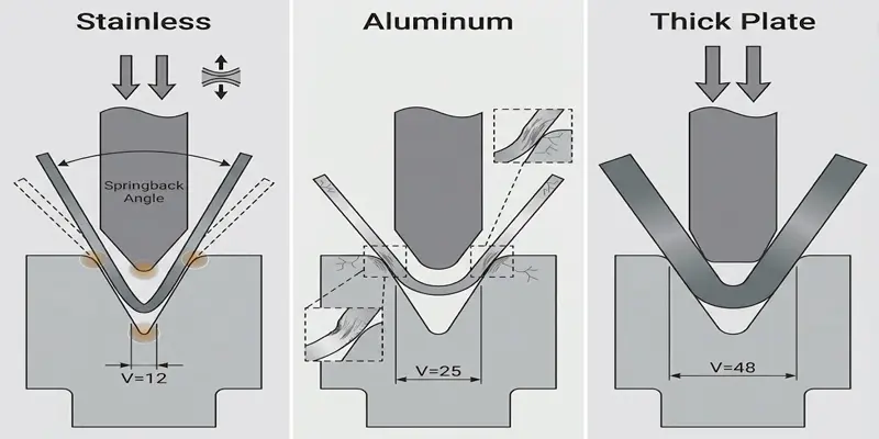
High-strength and stainless grades. Forming force scales with tensile strength — the standard practice is to multiply the baseline calculation by the ratio of the material’s tensile strength to the 60,000-psi baseline, and published material factors for common grades rise accordingly (austenitic stainless climbs well above mild steel, while soft aluminum sits below it). Stainless also springs back more than mild steel and work-hardens as it forms, so the common shop adjustment is to start at the upper end of the band — around 8–10 × t — to reduce cracking risk, tool load and angle sensitivity. Note that widening the die does not remove springback; it changes the compensation you have to apply. Verify with a trial bend on the actual batch before committing.
Soft and brittle aluminums. Soft aluminums form easily and often follow the punch nose rather than the opening, so a narrower die is geometrically possible — but the concentrated shoulder pressure marks cosmetic surfaces, and aluminum deserves extra care there. Brittle tempers are the opposite case: 6061-T6, for example, may require an inside radius of several times its thickness, which forces a wider opening than the thickness alone would suggest. Check the alloy’s minimum bend radius from the supplier’s data before selecting the die, not after — for demanding alloys, the manufacturer’s bending recommendations outrank any thickness multiplier.
Thick plate. At heavier gauges the quadratic relationship between thickness and force dominates — thickness squared divided by opening — so small thickness increases demand disproportionately more force. Thick-plate work also loads the die over fewer effective contact points, so the die’s rated load per metre and the machine’s centerline load limit both need explicit verification. Many plate shops deliberately run wider openings than the multiplier suggests, buying force headroom at the cost of a larger radius.
One caution that applies to every material: published multipliers and charts usually assume a baseline tensile strength, and they say nothing about your specific batch. Where the drawing is tight, measure the actual sheet thickness and check the mill certificate rather than the nominal grade.
The Three Constraints That Pull in Different Directions
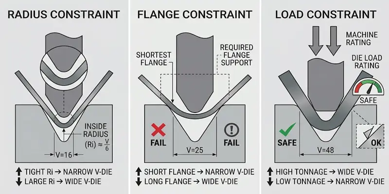
Here is the part most selection guides skip: the radius, the flange and the load each push the opening in a different direction, and on any real part one of them binds first. Identifying the binding constraint tells you which lever to pull — and which trade-offs are safe to accept.
Radius pulls you toward a specific opening. In air bending the natural inside radius lands at roughly one-sixth of the opening (for standard mild steel), so a drawing that needs a small radius caps how wide you can go, and a drawing that tolerates only a large radius sets a floor. The relationship also runs in reverse: if a 3 mm mild steel part needs an inside radius near 4 mm, the opening starts at 4 ÷ 0.16 ≈ 25 mm — and then the other two checks decide whether 25 mm survives.
Flange pulls you narrower. The flange must bridge the opening during the stroke; a common screening check for a 90° air bend puts the shortest supported flange at roughly 0.6–0.7 × the opening, depending on shoulder geometry and bend angle. Run the check in isolation and it is unforgiving: a 16 mm opening on 2 mm sheet needs roughly 11 mm of supported flange, so a 10 mm flange fails before tonnage is even discussed. A wider die can quietly disqualify a part that a narrower one forms fine.
Load pulls you wider. Force falls as the opening grows, in both the machine rating and the die’s load-per-metre limit. Wider is also kinder to the surface and to the tooling.
When two of them conflict, the diagnosis is usually one of the five rows below:
| The first thing that binds | What you see | Which lever to pull |
|---|---|---|
| Drawing radius is smaller than the natural radius | Formed radius exceeds the print | Try the next opening down after checking load; or a radius punch/die; or bottoming — accepting substantially higher force; or revisit the drawing |
| Flange too short for the opening | Edge slips toward the V during the stroke; unstable legs | Drop to a narrower opening and re-verify radius and load; or a sharp-shoulder die; or hem/redirect the bend line |
| Load exceeds the machine or die rating | Tonnage calculation over the limit | Open the die up (if radius and flange allow), shorten the formed length per hit, or move the job to a larger machine |
| Springback swamps the correction | Angle wanders across the batch | Narrower opening reduces die-width-related springback; but first rule out material variation — mixed batches corrupt every diagnosis |
| Marking rejects cosmetic parts | Burnished lines along the bend | Wider opening where the radius tolerates it; clean shoulders; protective film or dedicated low-mark tooling |
The order of operations matters. Fix the binding constraint first, then re-verify the other two, because every lever moves all three. A narrower opening solves the flange and raises the load; a wider one relieves the load and enlarges the radius and the flange demand. Run the loop until all three pass — and if the loop will not close with a standard V-die, that is not a failure of arithmetic; it is the drawing asking for different tooling, which is the subject of a later section.
Choosing From the Dies You Actually Own: A Worked Example
Selection charts return an ideal number. The machine floor returns a die ladder — the fixed openings your shop owns, whether as single-V dies or the four sides of a multi-V block. Real selection means walking the ladder, re-verifying the three constraints at each candidate opening.
The job: a bracket in 4 mm mild steel (about 450 MPa tensile), 90° air bend, 1,000 mm bend length, shortest flange 20 mm, inside radius not functionally critical. Machine: 100-ton-class press brake.
The starting point: 8 × 4 mm = a 32 mm opening. Suppose the rack holds V24, V32 and V40:
| Candidate | Ratio | Natural inside radius (≈ 0.16 × V) | Flange screening (≈ 0.6–0.7 × V) | Forming force (≈ 1.33 × σb × S² × L ÷ V) | Verdict |
|---|---|---|---|---|---|
| V24 | 6 × t | ≈ 3.8 mm | ≈ 14–17 mm — clears the 20 mm flange | ≈ 399 kN (≈ 40 t) | Feasible: more load, tighter radius than the print needs |
| V32 | 8 × t | ≈ 5.1 mm | ≈ 19–22 mm — borderline at 20 mm | ≈ 299 kN (≈ 30 t) | The ideal ratio, but the flange barely bridges |
| V40 | 10 × t | ≈ 6.4 mm | ≈ 24–28 mm — exceeds the 20 mm flange | ≈ 239 kN (≈ 24 t) | Rejected by the flange before load even comes into it |
The text-book choice (V32) sits right at the edge of flange support, and the comfortable-on-load choice (V40) is disqualified outright. The working answer is V24: the flange clears with margin, the load — about 40 tonnes on a 100-ton machine — leaves reasonable headroom, and the resulting radius is tighter than the drawing requires but functionally harmless. The correct punch nose radius sits just under the natural radius, and the die angle is 70° or shallower so overbending for springback never reaches the bottom of the V. (The metric shortcut in the table uses the 1.33 coefficient common in air-bending estimates for mild steel; published variants use slightly different constants, so treat the outputs as estimates and confirm against the tooling maker’s charts for anything near a limit.)
Two verification steps close the selection:
- Die load per metre. The ~40 t over 1 m is fine for a healthy standard die, but the check is against that die’s rating, not a category average — and on a multi-V block, against the rating for that particular opening, since shoulder material between adjacent openings may be thinner than the block’s headline rating suggests.
- Machine loading pattern. As a general rule of thumb, never apply full machine tonnage over a bend length shorter than about 60% of the distance between the side frames; shorter, heavier bends concentrate load where the ram and bed are designed to carry the least. This job is nowhere near the limit, but the check costs ten seconds.
Then run a trial bend on material from the same batch and measure the angle, the radius and the surface. The calculation predicted ~3.8 mm of radius and a load near 40 t; if the first article comes in close to both, the numbers were honest. If not, the sheet is telling you something the chart could not.
Common Selection Mistakes Worth Unlearning
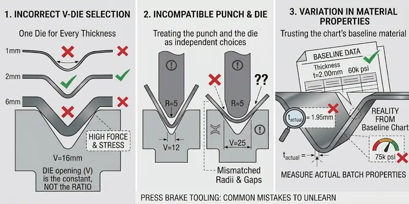
Most selection failures trace back to a handful of habits that no single calculation will catch:
- One opening for every thickness. A die that serves 2 mm sheet cleanly is badly oversized for 1 mm and dangerously undersized — in force terms — for 6 mm. The ratio, not the die, is the constant worth protecting.
- Treating the punch and the die as independent choices. The punch radius, the die angle and the opening interact; picking a die from the thickness chart and a punch from the shelf separately is how compatible-looking setups produce wrong radii. Tooling standards and mounting systems constrain the combinations further — our tooling compatibility guide explains what actually interchanges.
- Trusting the chart’s baseline material. Multipliers and charts are calibrated to a baseline tensile strength and nominal thickness. Your batch is neither, and tight drawings expose the difference.
Before You Release the Job: A Selection Checklist
A consistent routine beats memory, especially in high-mix shops. Run this sequence before every new bending job:
- Identify the material — grade, actual measured thickness, tensile strength, bending direction relative to grain.
- Confirm the bending method — air bending, bottoming or coining; the opening follows the process, not the other way round.
- Establish the required inside radius — from the drawing, estimate the opening and confirm it against the tooling maker’s data.
- Check the shortest flange — against the ≈ 0.6–0.7 × V screening value and the actual shoulder geometry.
- Calculate the forming force — with the real material values, and confirm both machine and die load ratings.
- Verify tooling compatibility — punch and die as a matched pair: standard, mounting, clamping, height, load capacity.
- Trial-bend on production material — measure angle, radius, flange and surface before releasing the batch.
- Record the approved combination — tooling, parameters and first-article results, so the next run starts from evidence instead of memory.
When a Standard V-Die Cannot Hit the Drawing
If the loop in the worked example will not close, the drawing is asking for something a standard V-die cannot deliver, and there are four established ways out:
- A tighter radius than air bending allows points to a radius punch or die, or to bottoming/coining with tooling selected for that process — accepting the higher load and the reduced angle flexibility, and verifying the ratings accordingly.
- A shorter flange than the opening supports may call for a sharp-shoulder die, a narrower opening, or special forming tooling that supports the part differently; very short flanges sometimes justify a dedicated approach rather than forcing the V-die to do the job.
- A cosmetic surface pushes toward wider openings (where radius allows), clean and polished die shoulders, protective film, or low-mark tooling — the mechanical side of a problem we cover separately in our article on preventing die marks and scratches on bent parts.
- No die in the rack fits is a tooling inventory question, not a bending one: if the same out-of-range requirement appears on consecutive jobs, the cheapest answer is buying the right die, and the right time to plan that is alongside the next tooling purchase.
It is also worth knowing when the die is not the problem at all. On long workpieces, machine and tooling deflection can make the middle of the bend differ from the ends no matter which opening you choose — that is a job for a crowning system, not a different V. And when a correctly selected die still produces wandering angles, the search should move to synchronization, angle measurement and material variation rather than more die swaps.
This is where machine and tooling decisions stop being separable. The openings a shop can afford to own, the die angles that keep air bending predictable, and the load ratings that make a heavier flange run safely all depend on the machine the dies bolt into — which is why we treat tooling selection as part of the machine conversation rather than an afterthought. If you are planning tooling around a new or existing brake, our tooling and tool storage solutions cover the systems we supply and support alongside our press brake range.
Frequently Asked Questions About V-Die Opening Selection
Can I use one V-die opening for several different thicknesses?
Sometimes, but the opening means something different for each sheet. A 24 mm V is 8 × t on 3 mm material and 6 × t on 4 mm — different force, different natural radius, different flange demand. Re-verify radius, load and flange every time the thickness changes rather than reusing a setup that worked last week.
Why does stainless steel usually need a wider opening than mild steel?
Austenitic stainless forms with more force per the same geometry, work-hardens during the bend, and springs back more. A wider opening trims the peak load and reduces cracking risk at the outside surface. Common shop practice starts around 8–10 × t and confirms with a trial bend on the actual batch.
What actually happens if the opening is too small for the job?
Forming force climbs with the inverse of the opening, so the immediate risk is exceeding the die’s load-per-metre rating or the machine’s centerline load — which can permanently deform tooling and, in the worst case, damage the ram and bed. Before that, you will usually see it coming as heavier marking, a tighter-than-planned radius and, on less ductile material, cracking along the bend.
The drawing radius is smaller than the natural air-bend radius. Do I just pick a narrower die?
Narrower is the first lever, but you are buying radius with force — check the load at the smaller opening before committing. If the required radius sits below what a 6 × t opening can deliver, the realistic options are bottoming or coining (with their higher loads), a radius punch or die selected for the job, or going back to the drawing to ask whether the radius is truly functional.
Can a CNC press brake select the V-die opening automatically?
Many advanced controls and offline programming packages carry tooling databases and can propose an opening from the library for each bend. The proposal is only as good as the tooling data behind it — the operator still needs to verify the actual material, the die’s load rating, the flange geometry and the machine setup before releasing the job.
How often should V-die tooling be replaced?
There is no universal interval. Inspect the V-groove and shoulders regularly for wear, deformation and surface damage, and recondition or replace the die when its condition starts to affect angles, surface quality or safe operation — not on the calendar.
Do I really need a trial bend if the calculation says the die is fine?
Yes — the calculation is a screening tool built on baseline material values, and it cannot see your batch’s thickness tolerance, yield variation or rolling direction. A first article bent on production material, with angle, radius and surface checked, is what converts a plausible selection into a production setup.
Conclusion
A sound V-die selection runs in the same order every time: confirm the bending method and the actual material, start the opening from the 6–8 × t band, then settle the conflict between radius, flange and load — and finish with a trial bend on the production batch. The multiplier exists to save you time; the three verifications exist to save you the setup that the multiplier would have cost you.
When the constraint loop will not close with standard tooling, treat it as useful information: the part is telling you what your tooling library is missing, and that is a procurement decision, not a floor improvisation. And if you are fighting a problem that no opening seems to fix — inconsistent angles on long parts, tooling loads you cannot get under, or a material that refuses every die on the rack — the fastest route is usually a second pair of eyes on the whole bending application.
Contact the CAMT team with your material grade, thickness, bend length, required inside radius and part drawings, and we will help you evaluate the machine configuration and tooling setup that fit the parts you actually make. The CAMT press brake range — from economical torsion-bar machines to multi-axis CNC and tandem systems — is built to work with the tooling and storage systems we supply and support.