Press brake tooling decides bend accuracy, inside radius, surface quality, setup time and tool life. The wrong punch or V-die produces angles that drift along the part, tonnage that exceeds what the tool can carry, marks on cosmetic sheet, interference that makes a bend physically impossible — and, at the extreme, a punch that fails under load.
Selection depends on more than sheet thickness. Material strength, bend geometry, tooling interface, machine capacity and production volume all have to agree with each other, and of those five, the interface is the only one that cannot be corrected later without buying different tooling.
This guide covers the tooling types, what the word “standard” actually means when it appears on a purchase order, the arithmetic that decides whether two tools can share one setup, and a selection sequence that follows the part rather than the catalogue.

1. What Is Press Brake Tooling?
Press brake tooling refers to the interchangeable upper and lower tools installed on a press brake to form sheet metal into specific shapes.
A typical tooling setup consists of two main components:
- Punch (upper tool): mounted on the ram, moves downward to press the sheet into the die.
- Die (lower tool): mounted on the machine bed, supports the material while determining the bending geometry.
When the ram descends, the punch pushes the sheet into or against the lower die, and the required bend is formed.
That is the narrow definition. In practice the word covers three different scopes, and confusing them is where tooling budgets go wrong.
The narrow scope is the punch and the die — the consumable pair that touches the metal. The working scope adds the punch holder, the die rail or die holder, the clamping system, and the crowning system underneath the die, because those parts decide whether the punch and the die actually meet squarely along the full bend length. The system scope adds everything needed to get the right tool into the machine quickly and correctly: segment layout, tool identification, storage, and the setup data that travels with each tool.
A press brake with good punches and dies in worn holders, sitting on an uncrowned bed, in a workshop where nobody can find the right segment, will bend worse than a modest machine with a coherent system.
The geometry and condition of the tools influence several production parameters at once:
| Tooling parameter | Effect on bending |
|---|---|
| Punch angle | Sets the sharpest angle the punch can form without interfering with the sheet |
| Punch tip radius | Influences the inside bend radius and how force enters the material |
| V-die opening | Affects bending force, inside radius, and minimum flange length |
| Die shoulder radius | Influences material contact, friction, and surface marking |
| Tool height | Determines available clearance and whether tools can share a setup |
| Tool hardness | Affects wear resistance and service life |
| Tool alignment | Influences bend consistency across the workpiece |
A fabricator bending stainless steel electrical cabinet panels may need polished tooling surfaces to control scratching, while a manufacturer producing deep enclosures may need gooseneck punches to clear flanges that are already formed. Neither requirement shows up in a thickness measurement.
The consequence is simple: tooling should be selected from the workpiece outward, rather than from whatever happens to be in the rack.
There is also a lifetime argument for treating tooling as a system rather than an accessory. Machines get replaced; a tooling library, if it is chosen well, outlives the machine it was bought for. That is the whole reason the interface decision in Section 3 carries more weight than the price of the tools themselves.
2. Main Types of Press Brake Tooling
Every punch profile is a trade between clearance and load capacity. A profile that reaches around a formed flange has less material behind the tip, and less material behind the tip means a lower rating for the same nominal height. That single sentence explains most of the selection mistakes covered in this section.
2.1 Standard Press Brake Punches

Standard punches are the most widely used upper tools in general sheet metal bending.
They feature a straight profile with a defined included angle and nose radius. The simple geometry suits common work: brackets, panels, channels, enclosure components, and general 90-degree bending in mild and stainless steel.
When selecting one, four numbers matter: the included angle, the tip radius, the overall height, and the rated load. The angle sets the sharpest bend the punch can produce without the sheet contacting the flanks; the height decides which tool families it can share a setup with; the rating decides how much of the machine’s tonnage it can actually take.
That last point deserves stating plainly, because it is where buying decisions go wrong. The tonnage rating belongs to the tool, not to the machine, and it does not transfer between profiles. A gooseneck is generally rated lower than a straight punch of the same height because the neck carries the load through a smaller section. That is not a manufacturing defect, it is geometry. The number you need is on the tool, in the catalogue, or in the documentation the supplier provides — and if a supplier cannot give you a rating in tons per meter or tons per foot for the specific profile and length, you are being asked to guess at a load limit.
2.2 Gooseneck Punches

Gooseneck punches have a recessed or curved body that provides clearance around flanges that are already formed.
During multi-stage bending, a straight punch can collide with an existing flange before the next bend is complete. That collision damages the workpiece, restricts the bending sequence, or makes the geometry impossible to produce at all. The recessed body of a gooseneck creates room for the formed material to pass.
Typical applications include deep U-channels, electrical enclosures, sheet metal boxes and housings, components with multiple return flanges, and any profile where clearance rather than force is the limiting factor.
Two cautions apply. First, not every gooseneck provides the same clearance — check the punch depth, the throat geometry, the working height and the rated load, because “gooseneck” describes a shape, not a capacity. Second, the reach is finite. A gooseneck buys clearance up to the depth of its throat and no further, and the intermediate bend orientations during the sequence are what actually decide whether it clears. Checking the finished part silhouette is not enough. That judgement is set out in our guide to bending deep boxes and cabinets without tooling interference, and it is worth reading before you specify a gooseneck “to be safe”.
2.3 Acute-Angle Punches

Acute punches have an included angle below 90 degrees, commonly 30, 45 or 60 degrees.
Their purpose is narrower than it first appears, and the distinction matters. In air bending, the punch included angle sets a floor on the angle you can produce: the sheet wraps around the tip, and once the bend passes the punch flanks the sheet and the tool interfere. So an 88-degree punch can hold a 90-degree part and cannot form a 60-degree one. If the drawing calls for an included angle sharper than your punch, you need a sharper punch — or a different bending method.
Springback compensation is a separate matter, and this is where the two ideas are often confused. In air bending, springback is offset by pushing the punch deeper, not by buying an acute punch: the achieved angle is set by penetration depth, so an 88-degree punch will happily produce 90 degrees, 92 degrees, or a slight overbend and release back to 88. What an acute punch adds is the ability to drive past an angle the flanks of a 90-degree punch would block.
Acute punches therefore earn their place in three situations: included angles below 90 degrees set by the drawing, pre-hemming where the edge is bent to 30–45 degrees before flattening, and bottoming or coining operations where the punch geometry defines the finished angle rather than the stroke.
Selection factors are the included angle, the tip radius, material thickness and strength, the final angle required, and available stroke and clearance. Do not assume an acute punch solves every sharp-angle job: the die opening and the bending method have to support the geometry too.
2.4 Radius Punches

Radius punches carry a larger or specially profiled nose for work that needs a rounded inside bend: large radii specified on the drawing, thick sheet, decorative panels, structural components, and applications where a small nose would over-deform the material.
The practical consequence is a stocking decision rather than a programming one. A radius becomes a tool you own, not a number you type. Once a product line requires a defined inside radius, that radius has to exist as ground tooling and stay in the library.
Punch radius is chosen from the drawing requirement, then checked against what the material will tolerate. In air bending, the resulting inside radius is not set by punch radius alone — die opening, material properties and bending conditions all move it, which is why the same punch produces different radii in different setups.
2.5 Offset and Z-Bend Punches

Offset punches form two opposing bends in a single stroke, producing an offset or Z-shaped profile: mounting brackets, reinforcement components, connectors, structural supports, and offset panels.
Punch and die have to be designed together around the offset height, material thickness, bend angles and available machine clearance. The setup is unforgiving — an offset tool that is slightly out produces two wrong bends at once — and for complex offsets, a purpose-built tool is often cheaper than stacking standard operations, because each extra operation brings its own handling and tolerance.
2.6 Hemming and Flattening Tools
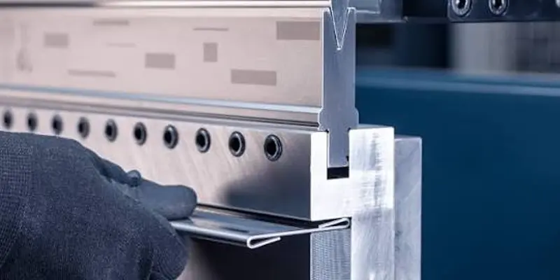
Hemming folds a sheet edge back onto itself to create a reinforced or finished edge. The process normally runs in two stages: pre-hemming, where the edge is bent to an acute angle around 30–45 degrees, and flattening, where dedicated tooling closes the fold to the required profile.
It appears in automotive components, cabinet doors, furniture panels, appliance housings, covers and protective panels.
The tooling must match the material thickness, the hem type and the final dimensions. Excessive flattening force damages the material or overloads the tooling, and hemming tooling is thickness-specific in a way that general punches are not — a hem set bought for 1.5 mm will not run 2 mm sheet simply because the machine has the tonnage.
2.7 Sectional and Segmented Tooling

Sectional tooling uses several shorter punch and die segments assembled to the required working length. Instead of one full-length tool, the operator combines segments to match the workpiece.
The advantages are real: flexible working lengths, easier handling, simpler storage, better access in box bending, and no need to buy a full-length tool for every job. For job shops running varied workpiece sizes and small batches, segmented tooling is usually the default.
The cost is that every segment is a joint, and joints are where load distribution and alignment get complicated. Differences in height, straightness or seating between adjacent sections show up as visible steps, inconsistent angles or localized defects. For long bends, verify segment tolerance and alignment before production, and treat a segment that has been reground differently from its neighbours — which is the subject of Section 4.
2.8 Special and Custom Press Brake Tooling

Standard tooling cannot cover every profile. Custom punches and dies are required when a component has unusual geometry, restricted clearance, special radii or demanding tolerances: deep-box and narrow-channel tooling, custom offsets, multi-bend tools, large-radius tools, non-standard V openings, and tooling for high-strength material.
The test for custom tooling is repetition, not difficulty. Will this geometry come back? A profile that solves a one-off costs more than the setup time it saves. A profile that solves a part family running every month pays back inside a quarter. Four situations genuinely justify it: a recurring part family with a geometry no standard profile clears; a radius or profile that is a product requirement rather than a process preference and must be held across suppliers; thickness and load combinations outside standard ratings; and a surface requirement that standard dies cannot meet without film, labor and rework.
Two situations look like custom tooling problems and are not. Inconsistent angles along a long bend are a crowning or machine issue. A part that will not release from the die is usually sequence and clearance. Neither is solved by a new punch.
When developing custom tooling, the supplier should review the part drawing, material specification, bending sequence, machine dimensions and tonnage requirements. CAMT provides custom press brake tooling and engineering support for specialized profiles and configurations.
One more thing about punch angles
The punch angle is not the part angle, and the two are confused more often than any other pair of numbers in this subject. An 88-degree punch can produce a 90-degree part or a 92-degree part, because in air bending the achieved angle is set by how far the punch descends into the opening rather than by the punch’s own included angle. A shop that buys a tool because the angle “should” produce the drawing dimension, and then cannot hold tolerance, has usually made this error. The mechanics behind it are covered in our guide to springback in sheet metal bending.
3. Common Press Brake Tooling Standards and Compatibility
The single most expensive compatibility decision is the interface. A punch can have the correct angle and radius and still be unusable, because its mounting interface does not match the upper tool holder.
Search for “press brake tooling standards” and you will find four competing explanations that talk past each other. They are not wrong; the word is doing three different jobs at once.
3.1 "Standard" Means Three Different Things
| What "standard" refers to | Who defines it | What it actually decides |
|---|---|---|
| Interface / clamping style | The machine and tooling makers, as de facto systems rather than one international document | Which tang geometry your holder accepts, and therefore which tools physically fit |
| Tooling build quality | The tooling manufacturer's own specification | Material grade, hardness and where it is applied, tip radius tolerance, straightness over length, segment interchangeability |
| Machine safety standard | Regional regulators and standards bodies | How the machine must guard the point of operation, and what the tool retention system must prevent |
Keeping these three apart is the most useful thing in this guide. A purchasing argument about “standards compliance” usually collapses because one party means the interface, another means the hardness spec, and a third means the guarding regulations — and no single document covers all three.
The common tooling families — European/Promecam, American, WILA New Standard, Trumpf, and the proprietary systems of Amada, Bystronic and LVD — belong to the first category only. They describe interface and clamping conventions, not one universal international dimensional standard.
3.2 European / Promecam Tooling
European or Promecam-style tooling is the most widely supported family in the world, which is why it is the default on a great many CNC machines built in Asia and Europe.
Its characteristics are an offset tang with a locating feature and a safety groove, held by a pressure plate acting on the side of the tang, with segmented punches as the norm and compatibility with a range of quick-clamping arrangements.
Amada-style tools sit in this family. The two are usually interchangeable in practice, but they are not identical: the locating details differ between makers, which is why “European” and “Amada” are better treated as one family with variations than as one specification. The name European-style also does not guarantee that every punch fits every European machine. Tang dimensions, safety features, punch height and holder geometry all have to be checked.
3.3 American-Style Tooling
American-style tooling is common on North American machines and uses a different mounting and clamping arrangement: a plain, centered tang seated in a wedge or screw clamp, usually with longer one-piece tools rather than segments.
It is robust and simple, historically strong in North America, and still common on heavy plate machines. The trade-off is access: the global library of European quick-change tooling generally requires adapters, and adapters add height and add a stack-up tolerance between the tool and the ram.
When replacing tooling, confirm the actual holder dimensions rather than the machine’s country of origin.
3.4 WILA New Standard Tooling
New Standard tooling — the WILA lineage, with Trumpf and Amada fixed-height systems as brand relatives — is a precision-oriented family designed for efficient tool changes and accurate positioning.
Its defining feature is a notched tang with a self-seating action and a safety click that allows vertical loading from below, so long tools do not have to be slid in from the end of the machine. The benefits follow from that: precision seating, quick-change compatibility, modular configurations, and integration with compatible hydraulic clamping.
It suits fabricators with frequent tool changes, complex parts and high-mix production. It also requires its corresponding holder or an engineered adapter, and it should not be assumed to fit conventional European or American holders directly.
Trumpf, Amada, LVD and Bystronic maintain their own families alongside New Standard. Some are functionally equivalent, some are deliberately not. The systems are sometimes discussed together because they share precision quick-change characteristics, but their interfaces should never be treated as interchangeable without verification — check the specific tooling generation, the holder arrangement and the machine configuration.
3.5 Brand-Proprietary Systems
Bystronic, LVD and Amada’s own fixed-height systems are proprietary or semi-proprietary interfaces optimized for their own machines. Compatibility depends on upper punch tang geometry, lower die base dimensions, clamping arrangement, tool centerline, tool height and machine-specific adapters.
| Tooling family | Main characteristics | Compatibility check |
|---|---|---|
| European / Promecam (incl. Amada-style tangs) | Offset tang, safety groove, segmented tools | Tang profile, locating detail, holder dimensions |
| American | Plain centered tang, wedge or screw clamp, longer one-piece tools | Upper and lower holder geometry |
| New Standard (WILA, Trumpf, Amada fixed height) | Notched tang, self-seating, vertical loading from below | Dedicated holder and locking interface |
| Brand-proprietary (Bystronic, LVD, others) | Machine-specific retention and positioning | Holder dimensions and written compatibility spec |
Similar-looking tooling is not necessarily interchangeable tooling. Before ordering replacement punches or dies, provide the machine manufacturer and model, the tooling interface, holder drawings, and dimensions taken from tools that already work.
One honest note before you plan a conversion: an interface change is a machine project, not a tooling purchase. You are replacing holders and clamping hardware on the ram and on the bed, not swapping a box of punches. That is why CAMT builds its press brake tooling clamping systems as retrofit kits with adapter bars for European, Amada, WILA and Trumpf geometries, rather than as a single proprietary line.
3.6 Tooling Build Quality: Four Questions
Build quality is the part suppliers compete on and buyers rarely specify, and it is the second meaning of “standard”.
A hardness figure on its own tells you very little. “52 HRC” means one thing when the whole tool is through-hardened and something else entirely when only the bending radius is locally hardened to a stated depth. Ask four questions and compare the answers:
- What is the base material, and what heat treatment does it receive?
- Where is the hardness applied, and to what depth?
- What is the tolerance on the tip radius, and how is straightness verified over a full-length tool?
- Are segments interchangeable — can a new 200 mm section be added to a ten-year-old set and still match height?
Whoever can answer all four in writing is a tooling supplier. Whoever answers the first two and changes the subject is selling catalogue steel.
3.7 Machine Safety Standards
The third meaning of “standard” has nothing to do with die openings or radii, and everything to do with keeping hands out of the tooling.
Machine safeguarding is the builder’s obligation, and tooling must not defeat it. In the United States, the general requirement is that the point of operation of a machine that exposes an operator to injury must be guarded — see OSHA 29 CFR 1910.212. That clause does not name press brakes specifically; it sets a general duty that applies to them. In Europe and the UK, press brakes fall under the current machine-tool safety standard for press brakes, EN ISO 6909:2026, which replaced EN 12622.
Nothing in that framework regulates the tool’s metallurgy. It regulates the guard and the retention. That is where the safety groove and the hook-type pressure plate on a modern clamp earn their place: they are not convenience features. A punch that is unclamped but still mechanically retained cannot fall on the operator’s hands or on the bed.
3.8 Six Measurements to Take Before You Buy
Compatibility is not a catalogue-diagram question. Two punches that look identical in a photograph can differ enough at the tang that one will not enter the holder at all. Before ordering anything — a new library, a replacement segment, or a set to go with a new machine — measure six things on tooling that already works, and put them on the purchase order.
| # | Measurement | Why it decides the purchase |
|---|---|---|
| 1 | Tang width and height at the clamping zone | The most common cause of "it looked right and does not fit" |
| 2 | Tang form — offset with safety groove, plain centered, or notched for self-seating | Determines whether the holder can grip and retain the tool at all |
| 3 | Locating feature — groove position, notch, safety button | Drives seating repeatability; mismatched features defeat the clamp's self-alignment |
| 4 | Tool height — punch overall height, die overall height | Sets your stack height, and therefore whether mixed profiles can share one setup (Section 4) |
| 5 | Die base width and shoulder geometry | Must sit correctly in the die rail or crowning system; a wide-base die in a narrow rail is a load-path problem |
| 6 | Rated load per meter, and over what supported length | The number to compare against the job, not against the machine's tonnage |
Measure with the tool in the condition you will use it, and clean the contact surfaces first. Burrs on a tang, a mushroomed top face or a hammered locating groove all read as “wrong size” if you measure a damaged tool and conclude the standard is different.
4. Stack Height: Why Mixed Tooling Heights Cost You Setups
This is the mechanism most tooling guides skip, and it accounts for a large share of setup time in a job shop.
Every punch has a height. Every die has a height. Add them, add the material, and you have the closed stack. For the machine to work, that stack has to sit inside the machine’s open height with room to load the part, and it has to be tall enough that the ram can reach the material before it runs out of stroke. Too short a stack and you need risers or shims. Too tall and it will not go in at all.
Now consider what happens when the six punches a job needs have six different heights, or when the gooseneck die is shorter than the V-die. Each height difference changes the closed stack, which changes how far the ram must travel, which means tools that do not share a shut height cannot all be in the machine at the same time. You get four setups where you expected one, and every changeover drags the part back to the bench — which is the part of tooling cost that never appears on a quotation.
Fixed-height punch families and common-shut-height dies exist to solve exactly that. When every punch in the family has the same overall height, and the dies are built so that the bottom of the die opening sits at a common height, mixed profiles can be loaded across the bed simultaneously and will all close together. That is how a shop produces 90-degree bends, 30-degree bends, offset bends, flattening and several inside radii in a single setup, with any punch and die combination in the brake at the same time and no risk of a height mismatch crashing a tool. It is documented in the trade press as a deliberate system design rather than an accident of dimensions (Canadian Metalworking, “New Takes on Press Brake Tooling”).
The same idea appears from the die side in the commentary carried by Shop Metalworking Technology: standardizing the effective V-height means an offset tool, a radius tool and a hemming tool can all be in the machine at once and bottom out together, which lets a shop build common tool layouts across a wide range of parts and thicknesses without shimming.
Two practical consequences follow, and both are decided once.
If you buy into a common-shut-height system, buy into it deliberately. The system’s value comes from the library being complete — enough profiles at the same height to cover your recurring work. A partial conversion gives you the cost without the single-setup benefit, and you will still be shimming.
Regrinding breaks the system. When a worn punch is reground, it gets shorter. In a mixed-height shop that is a small nuisance. In a common-shut-height library it silently removes the tool from the family: it no longer closes with the others. Either track regrind removal and compensate with a shim of the same thickness, or retire the tool from the shared-height set. Nobody warns you about this at the point of purchase, and it is the reason some shops find their “system” quietly degrading after three or four years.
One more item belongs here, because it is the part of the stack fabricators forget to buy: the die support. A die sitting on an uncrowned bed will produce a different angle in the middle of a long bend than at the ends, and no tooling choice fixes that. Compensation is a machine feature, specified at purchase rather than added later.
5. How to Choose the Right Press Brake Punch and Die
Selecting tooling means evaluating several factors together, and the order matters. Work through the inputs below in sequence and the outputs follow from them.
5.1 Identify the Material Type and Thickness
Material properties drive bending force, springback and required tooling geometry, and different materials respond differently to the same setup.
| Material | Bending consideration | Tooling consideration |
|---|---|---|
| Mild steel | Relatively predictable air-bending behavior | Standard punches and V-dies for general work |
| Stainless steel | Higher strength and greater springback than mild steel | Adequate load capacity, suitable radii, polished contact surfaces |
| Aluminum | Sensitive to surface damage and cracking depending on alloy and temper | Appropriate punch radius and surface protection |
| High-strength steel | Higher bending force and significant springback | High-capacity tooling and verified load ratings |
| Copper and brass | Material-specific ductility and surface requirements | Suitable radii and surface-finish control |
Always identify the actual grade, tensile strength, thickness tolerance and temper. Bending 3 mm stainless steel is not the same job as bending 3 mm mild steel; the higher strength can raise the required force by a margin that takes the tool above its rating.
5.2 Select the Correct V-Die Opening
The V-die opening is the single most consequential number in air bending. It sets the required tonnage, the resulting inside radius, the minimum flange length, the contact pressure, and the marking risk.
A common starting range for air bending mild steel is:
V = 6t to 10t
where V is the die opening and t is material thickness. Many fabricators begin at approximately V = 8t. For 3 mm mild steel, that is an opening of 24 mm.
| Material thickness | 6 × t | 8 × t | 10 × t |
|---|---|---|---|
| 1 mm | 6 mm | 8 mm | 10 mm |
| 2 mm | 12 mm | 16 mm | 20 mm |
| 3 mm | 18 mm | 24 mm | 30 mm |
| 4 mm | 24 mm | 32 mm | 40 mm |
| 5 mm | 30 mm | 40 mm | 50 mm |
| 6 mm | 36 mm | 48 mm | 60 mm |
| 8 mm | 48 mm | 64 mm | 80 mm |
| 10 mm | 60 mm | 80 mm | 100 mm |
These are starting points, not tooling specifications, and the range has a floor. Below roughly six times thickness, tonnage climbs steeply and the risk of cracking or die damage climbs with it. A narrower opening does give a smaller inside radius, but past that point you are buying radius with force and with the margin between the tool’s rating and the job. When a tight radius is the real requirement, a radius punch or a radius die is usually cheaper than forcing a narrow V.
In the other direction, a wider opening reduces force, reduces marking and increases the inside radius — but the flange then has to be long enough to reach both shoulders, which is the constraint that rejects more die choices than tonnage does.
For thicker material, high-strength alloys or critical radii, use the tooling manufacturer’s bending charts and verify the actual load requirement rather than scaling from a table.
5.3 Determine the Required Inside Bend Radius
For conventional air bending, a usable initial approximation is:
Ri ≈ 0.16V
For a 24 mm opening, that gives an inside radius of about 3.84 mm.
This is an approximation for air bending with a standard shoulder geometry and a material behaving close to mild steel — not a guaranteed result. The actual radius depends on material strength, ductility, punch geometry, die opening and bending conditions. If a drawing specifies a critical inside radius, verify the configuration against the tool manufacturer’s data and confirm it with a trial bend.
5.4 Choose the Appropriate Punch Tip Radius
The punch tip radius controls how force enters the sheet.
Too small a tip concentrates stress and contributes to surface damage or cracking, particularly in less ductile material. Too large a tip can prevent the required inside geometry from forming at all. The factors are material thickness, ductility and tensile strength, the required inside radius, the bending method and the surface finish requirement.
The recurring error is assuming the tip radius sets the finished radius. In air bending it does not — the opening and the material behavior dominate. The tip radius sets the minimum the punch can impose and the stress pattern it creates.
5.5 Check the Required Bend Angle
Punch angle and die geometry have to accommodate the operation, and the four cases are distinct:
- 90-degree bending uses standard punch and die configurations.
- Acute-angle bending needs either a punch with a sharper included angle or a different bending method.
- Large or open-angle bending depends on tool geometry and machine clearance rather than on the angle alone.
- Hemming requires dedicated pre-hemming and flattening tooling, matched to thickness.
The programmed punch angle will differ from the finished bend angle because of springback. A setup that relies on tooling angle alone, with no compensation, will miss on anything but the material it was trimmed for.
5.6 Verify Minimum Flange Length
The minimum flange length is the shortest flange a given V-die and setup can form reliably. If the flange is too short, it cannot maintain stable contact with both die shoulders, and the results are unstable bending, inconsistent angles, material slipping, deformation next to the bend line, and a part profile that will not repeat.
Minimum flange depends on opening, shoulder geometry, material thickness, bend angle and tooling design, and it is the constraint most often discovered after the die has been ordered. In the sequence used here, flange length is checked before the opening is confirmed, because a die that meets the radius requirement and not the flange requirement is still the wrong die.
5.7 Confirm the Load Capacity
The machine and the tooling have two separate limits, and the job has to satisfy both.
Required tonnage depends on material tensile strength, sheet thickness, bend length, die opening and bending method. Force rises steeply as the opening narrows and scales roughly with the square of thickness, so doubling thickness at the same opening takes you close to four times the force — which is why a die that is comfortable in 3 mm is not automatically usable in 6 mm.
Two habits prevent most capacity failures:
Compare against the tool, not just the machine. The press brake’s tonnage and the tool’s rated load per meter are different numbers with different margins, and the smaller one governs.
Evaluate the station, not the average. A 200-tonne machine does not confer 200 tons on a 200 mm segment in the middle of the bed. That segment carries the load of that bend, and the rest of the bed does not help it. Short segments in high-tonnage work are where tools get overloaded while the machine readout looks comfortable.
Concentrated loading deserves particular attention. Never exceed the rated capacity of the machine, the punch, the die, or the clamping system, and check whether the tool’s rating assumes full-length support or permits point loading.
6. How Bending Methods Affect Tooling Selection
Three methods are in general use, and the choice changes what the tooling has to survive as much as what it has to produce.
6.1 Air Bending
Air bending is the default in modern press brake work. The punch pushes the sheet into the die without forcing it into full contact with the die surface, and the finished angle is controlled by how deep the punch travels.
The advantages are lower tonnage than the alternatives, flexibility across angles with the same tooling, a smaller tooling inventory, faster setup for mixed production, and compatibility with CNC angle compensation. The cost is sensitivity: angle depends on accurate punch positioning, consistent material, and correct springback handling. Air bending is where most of this guide’s ratios apply.
6.2 Bottoming
Bottoming pushes the material into closer contact with the punch and die surfaces, so the workpiece is formed against more of the tooling geometry than in air bending. It generally requires greater force and is more sensitive to tooling geometry, because the tools — not the stroke — define the angle.
Under the right conditions bottoming improves angle repeatability and reduces variation from some material effects. It also concentrates wear on the tool surfaces that do the forming, and it fails quietly when the machine cannot supply the force the geometry demands.
6.3 Coining
Coining is high-force forming in which the punch compresses the material heavily at the bend line, used where the forming characteristics have to be exact.
Compared with air bending, coining can require substantially more force and imposes far greater stress on the punch, the die, the machine frame and the clamping system. Coining should never be treated as air bending with a smaller V opening. The tooling and the machine both have to be rated for it specifically, and the die has to be built for it rather than borrowed from an air-bending set.
| Factor | Air bending | Bottoming | Coining |
|---|---|---|---|
| Tool contact | Partial contact with the die | Closer contact with die surfaces | Heavy compression at the bend line |
| Tonnage | Relatively low | Higher | Very high |
| Angle flexibility | High — set by stroke depth | More tooling-dependent | Tool geometry-dependent |
| Tooling requirements | General-purpose tooling | Matched punch and die geometry | Specialized high-load tooling |
| Typical application | General sheet metal fabrication | Repeatable bend profiles | Specialized precision forming |
For most general-purpose CNC work, air bending gives the practical balance between flexibility, tooling cost and efficiency. The other two are chosen for a reason, and that reason is usually a geometry or a repeatability requirement — not a shortcut on tonnage.
7. Press Brake Tooling Materials, Hardness and Service Life
Tooling material and heat treatment determine performance and life. In service, punches and dies see repeated compression, friction and contact stress, and poor material selection or inadequate heat treatment shows up as premature wear, deformation or cracking.
7.1 What the Material Has to Deliver
Tool steel selection balances core toughness, surface hardness, wear resistance, fatigue resistance and resistance to deformation, against how well the grade responds to heat treatment. Those properties conflict: a grade taken to high hardness for wear resistance loses toughness, and a tool that is hard but brittle fails suddenly under impact rather than wearing out gradually.
The application decides the balance. High-volume bending in abrasive material argues for wear resistance. Interrupted or impact-prone work argues for toughness. A tool used occasionally on light sheet does not need the same specification as one running three shifts, and paying for the difference without needing it is as much a mistake as under-specifying.
7.2 Why Heat Treatment Matters
Heat treatment is what turns a grade into a tool. Manufacturers use vacuum heat treatment, induction hardening or other controlled processes depending on the material and the geometry.
The objective is surface hardness with adequate core support behind it. Hardness without toughness increases the risk of brittle failure under impact or overload — the failure mode that produces fragments rather than a worn edge. This is also why the hardness figure quoted in a catalogue is only meaningful together with where it is applied and to what depth, the question set out in Section 3.6.
7.3 Why Precision Grinding Matters
Good steel does not guarantee accurate bending if the geometry is inconsistent. Grinding is what holds the punch tip radius, the die opening dimensions, the shoulder geometry, straightness, parallelism, and a consistent working height.
The last of those is the one buyers overlook. A consistent working height across the library is what makes a shared setup possible, which is the whole argument in Section 4 — and a grinding process that holds radius but drifts on height quietly defeats it.
These factors matter more, not less, as the number of segments across a long bed increases. For high-volume production, tooling accuracy and batch consistency feed directly into setup time, scrap rate and finished-part quality.
8. Press Brake Tooling Clamping Systems
The clamping system decides how punches and dies are installed, positioned and held. It matters for operator safety first and production efficiency second, and it is the component most often left out of the machine specification.
8.1 Manual Clamping Systems
Manual systems use mechanical fasteners or locking mechanisms to secure tooling. They are simple, inexpensive, easy to maintain, and adequate where tool changes are occasional.
The cost is time: installation, tightening and alignment all happen by hand. Where tools change several times a shift, manual clamping becomes the bottleneck, and the loss does not appear as a line item anywhere.
8.2 Hydraulic Clamping Systems
Hydraulic systems use hydraulic pressure to secure and release tooling, which brings faster changes, more consistent clamping force, less manual adjustment, and better efficiency where changeovers are frequent.
They suit CNC machines and high-mix work, and hydraulic clamping has become the norm in production environments rather than an upgrade. The system has to be matched to the machine and to the tooling interface — a correct clamp on the wrong holder still will not seat a tool.
8.3 Pneumatic Clamping Systems
Pneumatic clamping uses compressed air to operate the retention mechanism, and can give rapid tool changes in suitable applications.
Before installation, verify the air supply, the operating pressure, holder compatibility and the required safety features. Pneumatic systems are only as reliable as the air supply behind them, which is a maintenance consideration as much as a technical one.
| Factor | Manual | Hydraulic | Pneumatic |
|---|---|---|---|
| Initial investment | Generally lower | Generally higher | Application-dependent |
| Tool change | Manual operation | Powered operation | Powered operation |
| Setup efficiency | Suited to occasional changes | Suited to frequent changes | Suited to frequent changes |
| Maintenance | Mechanical inspection | Hydraulic system inspection | Air supply and pneumatic components |
| Typical application | Conventional workshops | CNC and high-mix production | Automated or semi-automated setups |
Clamping force also distributes differently. Point loading from screw clamps concentrates force on a small area of the tang, while wedge and hydraulic clamps spread it — which is why tang deformation is often a clamp-design symptom rather than a tool defect, as covered in Section 9.
CAMT supplies press brake tooling clamping systems in manual, hydraulic and pneumatic configurations. The right arrangement follows from the existing machine, the tool interface and the changeover rate, not from the clamp alone.
9. Common Press Brake Tooling Problems and How to Avoid Them
Even when the machine is working correctly, tooling selection or tool condition can create serious production problems. The five below cover most of what reaches a service desk, and the diagnostics at the end are what shorten the conversation.
9.1 Inconsistent Bend Angles
Likely causes are uneven punch and die alignment, worn or damaged tooling, inconsistent material thickness, an incorrect V-die opening, insufficient crowning compensation, and differences in material strength.
Work through it in order: inspect punch and die condition, check seating and alignment, verify the material specification against what was programmed, recheck the bending parameters, then check the crowning and compensation settings.
For long workpieces, machine deflection produces a different angle at the center than at the ends regardless of tool condition. A press brake crowning system compensates for beam and bed deflection, and it is the correct answer to that specific pattern — not a tooling change.
9.2 Surface Scratches and Die Marks
Causes include rough or damaged tool surfaces, sharp die shoulder edges, excessive contact pressure, material pickup on the tooling, an incorrect opening, and no surface protection.
The fixes are inspection and cleaning, polished or suitably finished tooling, an appropriate V opening, protective film or urethane inserts, and replacing damaged tooling rather than polishing around it.
For stainless and cosmetic work, surface finish is a tooling selection criterion, not a post-production problem to be polished out. The mechanics and the tooling options are set out in our guide to preventing die marks and scratches.
9.3 Tool Wear and Premature Failure
Excessive tonnage, the wrong tool material, inadequate heat treatment, repeated impact, poor maintenance and incorrect clamping or seating all shorten life.
Verify the maximum allowable tooling load, select material suited to the application, inspect working surfaces on a schedule, follow the manufacturer’s maintenance instructions, and take damaged tools out of service rather than keeping them in rotation.
Failure modes are worth recognizing by shape. Tip flattening and radius growth come from cumulative load, sometimes one overload, and can only be managed if the radius was recorded when the tool was new. Tang deformation — mushroomed, burred or flattened — means the tool no longer seats the way the holder expects, and it is permanent. Chipping and tip fracture are almost always load, and almost always predictable from the rating: a gooseneck asked for straight-punch tonnage will fail at the neck, and it does not fail gradually.
9.4 Tooling Compatibility Problems
Wrong tooling standard, incorrect tang dimensions, incompatible clamping, incorrect tool height and improvised adapters are the usual causes.
Before ordering, confirm the machine manufacturer and model, the upper and lower holder types, the punch tang dimensions, the die base dimensions, the working height and centerline, and the retention and safety features. The six measurements in Section 3.8 are the practical version of that list.
Never force an incompatible punch into a holder, and never compensate for a mismatched interface with improvised modification. A punch that has been persuaded into place is a punch that will move under load.
9.5 Material Cracking at the Bend Line
Likely causes are a punch radius that is too small, excessive strain, bending across the grain rather than along it, low ductility, and an inappropriate V-die.
Review the grade and thickness, increase the inside radius where the design permits, select a suitable opening, check the grain direction, and run trial bends before production.
Cracking is not necessarily a tooling defect, and treating it as one wastes money on punches that cannot fix a material problem. Our article on sheet metal cracking at the bend line covers how to tell a ductility failure from a radius failure.
9.6 Three Diagnostics Worth Memorizing
If the error follows the tool, it is the tool. A specific punch that produces a specific angle error wherever it is used is a tooling fault. Stop calibrating the machine and inspect the tool. This is the fastest diagnostic in the shop.
If the error is worst at the center of a long bend, it is deflection. That is crowning or the machine, not the die.
If the tools will not close together although they are the same style, it is stack height. Section 4 explains why, and it is a library design issue rather than a machine fault.
9.7 Do Not Fit Tooling More Precise Than the Machine
This is the most expensive mistake in the whole subject, and it is invisible on a quotation.
Do not fit a tooling system significantly more precise than the machine it sits on. Precision tooling can only improve repeatability up to the limit of the machine’s own positioning, parallelism and deflection. Beyond that limit you have paid for tolerance the machine cannot use, and you have installed a system that will show every one of the machine’s weaknesses as though they were tooling faults. The warning is made directly in Canadian Metalworking’s account of low-cost changeover improvements, alongside the cheap fixes that often deliver more: marking tools to match the setup sheet, staging them beside the brake, and using self-seating tooling instead of seating punches with a block of wood.
10. How to Maintain Press Brake Tooling
Regular maintenance holds dimensional accuracy, delays wear, and prevents the unplanned stoppage that always happens on the wrong job.
| Interval | Checks |
|---|---|
| Daily | Visible damage on punches and dies; metal particles and debris on working surfaces; clamping and locking mechanisms; correct seating; visible wear or deformation |
| Weekly | Die shoulders and punch tips for wear; alignment across segmented tooling; clamping components; recurring angle or surface complaints logged during the week |
| Periodic | Measured punch and die dimensions against the original record; straightness and parallelism; condition against manufacturer specification; clamping system and mounting surfaces; retirement decisions for tools beyond wear limits |
10.1 Record Before You Can Manage
Two numbers make the whole schedule work: the tip radius and the overall height, recorded when the tool is new. Without them, “worn” and “was always like that” are indistinguishable, and every inspection becomes an opinion. Measure at replacement, re-measure at intervals, and compare the height against its original value — in a common-shut-height library that comparison is not housekeeping, it is what keeps the library functional.
10.2 Storage and Handling
Tooling should live in a clean, dry place, and the three failures that account for most loss are worth naming.
Contact damage. Punches stored tip to tip, dies stacked without separation and tools sliding against each other in a drawer produce the nicks that later appear as marks on parts. Wipe tools after use, apply a light film of oil, and store them without contact between working surfaces. This is standard practice in the trade press and it is still widely skipped (Shop Metalworking Technology).
Distance from the machine. Tooling stored across the shop, or behind a forklift, turns a two-minute change into fifteen. Keep the set at the machine, in a cabinet or a mobile station, so the operator never leaves the workcell to fetch a die. CAMT’s tooling storage and tool station solutions are built around that, including loading arms rated for tools heavy enough that lifting them is itself a risk.
No identification. A tool that cannot be identified cannot be tracked, and unknown tools end up in the wrong setup. Mark every tool with an identifier that matches your setup sheet, and record its rating, height and radius. At the simple end that is an etched number and a paper register. At the automated end it is a data-matrix code on the tool that a control or an app can read, with the geometry and load limit travelling into the program — the principle behind WILA Smart Tooling and its Bluetooth connection to the clamping bar. The value is not the technology. It is that the operator stops retyping dimensions, and retyping dimensions is where tool crashes come from.
11. How to Select Press Brake Tooling When Buying a New Machine
Tooling requirements belong in the machine decision, not after it. A machine with adequate tonnage and bending length will still fail to meet expectations if the tooling configuration cannot sit inside it.
11.1 Start From the Parts You Actually Make
Identify the main material types, the minimum and maximum thickness, the maximum bend length, the common bend angles, the required inside radii, the deepest box or return flange, and daily volume. That set of answers determines the punch families and openings you need — and, just as often, tells you that a machine under consideration has the wrong open height for the work.
11.2 Check Opening, Stroke and Tool Height Together
The available opening and stroke have to accommodate both the tooling and the workpiece geometry. Verify the maximum tool height, the die setting height, the ram stroke, the machine open height, punch and die clearance, and workpiece interference during bending.
These are the inputs to the closed-stack calculation in Section 4, and this is where that arithmetic earns its keep. A short stack needs risers or shims. A tall stack will not fit. A library of mixed heights multiplies the setups. Any of the three can be designed out at purchase and only at purchase.
11.3 Weigh Changeover Frequency Honestly
Where many components run in small batches, quick clamping and a common-height library are worth the investment. Where a few parts run in long campaigns, a conventional arrangement is sufficient and the money is better spent on tooling quality.
The decision belongs to total production efficiency, not to the price of the clamp. A shop that changes tools twice a shift will never recover a hydraulic system; a shop that changes ten times a shift recovers it in months.
11.4 Plan Crowning and Accuracy Together
Long bends produce uneven angles because the machine structure deflects elastically. Crowning compensates for that, and the tooling, the clamping system and the crowning arrangement have to be assessed as one package — a crowning system under a die that does not seat squarely is not a cure.
11.5 Look One Product Generation Ahead
A machine should handle the work you expect to quote, not only the work you run today. A shop planning to move into more complex enclosures will want additional profiles, quick-change clamping, multi-axis control, angle measurement, and a more capable crowning arrangement — and will want the open height and stroke that let those fit later.
CAMT builds several CNC press brake configurations, including conventional CNC, electric, tandem and heavy-duty machines. The right configuration follows from material range, bending capacity, volume and automation requirements — and, as often as not, from the tooling plan rather than the other way round.
12. Press Brake Tooling Selection Checklist
Use this before committing to a purchase or an installation. Each row is a decision that is cheap now and expensive later.
| Inspection item | What to verify |
|---|---|
| Machine model | Manufacturer, model, and machine specifications |
| Tooling standard | European, American, WILA/New Standard, Trumpf, or brand-proprietary — stated by name, not by country |
| Upper tool interface | Tang width and height, tang form, locating feature, safety groove, clamping geometry |
| Lower tool interface | Die base width, shoulder geometry, mounting arrangement |
| Material | Grade, tensile strength, and ductility |
| Thickness | Minimum and maximum sheet thickness |
| Punch geometry | Included angle, tip radius, overall height, rated load |
| Die geometry | V opening, shoulder radius, rated load per meter |
| Bending method | Air bending, bottoming, or coining |
| Required radius | Target inside bend radius, and whether it is achievable in this material |
| Flange dimensions | Minimum flange on the real part, checked before the opening is confirmed |
| Stack height | Punch height plus die height plus thickness, against open height and stroke |
| Machine capacity | Available tonnage, and the rated load of the tool at that station |
| Tool condition | Wear, damage, straightness, alignment, and recorded height against original |
| Identification | Whether every tool carries an identifier matching the setup sheet |
| Production requirements | Changeover frequency and expected service life |
12.1 What to Send With a Tooling Inquiry
For a quotation that does not come back with questions, provide:
- Press brake manufacturer, model, and year.
- Tooling family and clamping system, with photographs of the current holder.
- The six measurements from Section 3.8, taken from tools that already work.
- Material type, grade, and thickness range.
- Maximum bending length and the tightest flange on the real parts.
- Required bend angles and inside radii, and whether they are drawing-critical.
- Expected tonnage, or the heaviest job in the mix.
- 2D or 3D part drawings, and the intended bending sequence if it is already fixed.
Complete information at the start reduces design revisions and installation problems more reliably than any other single step.
13. How CAMT Supports Press Brake Tooling and Bending Solutions
Choosing tooling is not a matter of buying a punch and a die. The tooling has to work with the machine, the material, the bending method and the production pattern — and when those four are specified together, the interface decision is made once, correctly, instead of being discovered at the first job.
Press brake machine configuration. CAMT offers CNC, electric, tandem and heavy-duty press brakes, specified by bending length, required tonnage, material thickness, control requirements and production volume. The press brake range sets the open height, stroke, crowning and clamping options that any tooling plan has to live inside.
Tooling clamping and compatibility. Manual, hydraulic and pneumatic clamping with adapter options for different tooling interfaces. Because an interface change is a machine project, these are supplied as retrofit kits rather than as a single proprietary line — the subject of Section 3.5.
WILA Smart Tooling. For work that needs fast changeovers and precise positioning, WILA-compatible smart tooling carries tool geometry and load limits from the tool itself into the control. Explore WILA smart tooling solutions.
Crowning and compensation. Mechanical and motorized crowning to compensate for beam and bed deflection on long workpieces, so that the center of a bend holds the same angle as the ends — see press brake crowning systems.
Tool storage and changeover. Cabinets, mobile tool stations and loading arms that keep the tool set beside the machine and take the weight of heavy dies off the operator. Explore press brake tooling and storage solutions.
To configure a package, we need five things from a fabricator: the material and thickness range, the tightest inside radius and shortest flange on real parts, the deepest box or return flange, an estimate of changeovers per shift, and six measurements or photographs of any tooling you intend to keep. From there the sequence is the one this guide describes — interface first, then stack height strategy, then profiles sized to the parts, then clamping and storage to match the changeover rate. Our application engineers will also tell you when a job points at a different machine rather than a different tool.
Start anywhere in this series
Tooling decisions branch from here, and each branch has its own arithmetic.
Frequently Asked Questions About Press Brake Tooling
What are the main types of press brake tooling?
Standard straight punches, gooseneck punches, acute-angle punches, radius punches, offset and Z-bend punches, hemming and flattening tools, segmented tooling, and custom punches and dies. Each covers a different combination of clearance, angle and load capacity, so the types are chosen by what the part needs to clear rather than by preference.
What are the most common press brake tooling standards?
Four interface families cover most machines: European/Promecam (including Amada-style tangs), American, New Standard (WILA, with Trumpf and Amada fixed-height relatives), and brand-proprietary systems. They use different tang geometry and clamping, so none is interchangeable with another without an adapter. Note that “standard” here means the interface only — tooling build quality and machine safety standards are separate subjects.
How do I choose the correct V-die opening?
For general air bending of mild steel, start at about eight times material thickness, within a practical range of six to ten times. Below roughly six times, tonnage rises steeply and cracking risk rises with it. Then adjust for the required inside radius and the shortest flange on the part, and check the resulting force against the tool’s rating.
Does the punch tip radius determine the inside bend radius?
Not by itself, and in air bending usually not primarily. The inside radius follows the die opening and the material behavior, at roughly 0.16 times the opening for mild steel. The tip radius sets the minimum the punch can impose and how the stress is distributed. For critical radii, use the tool manufacturer’s data and confirm with a trial bend.
Can I use the same press brake tooling on different machines?
Only when the holders, interfaces, dimensions and load ratings all match. Similar-looking tangs are not interchangeable. Adapters exist for most conversions, but they add height and add a tolerance stack between the tool and the ram, which is why shops running mixed standards keep adapters for exceptions rather than for daily work.
Why do my tools not close together even though they are the same style?
Almost certainly different stack heights. If the punches are not all the same overall height, or the dies do not share a common shut height, the tools cannot all be in the machine at once and close as a set. That is a library design issue, not a machine fault — and if it appeared gradually, check whether a reground punch has dropped out of the family.
How do I know if my press brake tooling is overloaded?
Overload is usually abrupt: a chipped or flattened tip, a deformed tang, a bend that suddenly will not form. Wear creeps in over months as radius growth, polishing and a widening bright band on the shoulders. Visual inspection cannot establish whether a tool is running within its rating, so calculate the force and compare it with the manufacturer’s allowable load per meter.
What is the difference between air bending and bottoming tooling?
Air bending uses partial contact between sheet and die, with the angle controlled by punch penetration and a given tool set covering many angles. Bottoming forces the material into closer contact so that the tool geometry defines the angle, which generally requires more force and matched punch and die geometry.
How often should press brake tooling be replaced?
There is no universal interval, and calendar-based replacement wastes good tools. Use measurable triggers instead: tip radius grown beyond the drawing tolerance, overall height reduced enough to break the shared-height set, a deformed tang, or a straightness deviation visible along the working length. Record both numbers when the tool is new so the comparison is possible.
Is segmented press brake tooling better than full-length tooling?
Neither is universally better. Segments give flexible working lengths, easier handling and simpler storage; full-length tools suit long repetitive bends and eliminate joint alignment as a variable. The deciding factors are workpiece size, production mix, and whether the segments can be kept matched in height over their life.
What information should I provide when requesting a press brake tooling quotation?
Machine manufacturer, model and year; the tooling family and clamping system; six measurements from tooling that already works; material grade and thickness range; maximum bend length and the tightest flange; required angles and inside radii; expected tonnage; and part drawings. Section 12.1 lists the full set.
Conclusion
Selecting press brake tooling is a balance between geometry, material, machine capacity and production pattern. Get the punch, die and opening right and you hold consistent angles, control the inside radius, protect the surface and stop wearing tools out early. Get the interface wrong and none of that matters, because the tool will not go in.
The order that works is the order in this guide: confirm the interface first, then decide the stack-height strategy, then size the profiles to the parts, then match clamping and storage to how often you change over. Most tooling money is lost in the first two steps, and both are decided once.
If you are specifying a new press brake, replacing an existing library, or working through a profile that standard tooling will not clear, send CAMT your machine details and part drawings. Our engineers will tell you what fits, and when the answer is a different machine rather than a different tool.