Sheet metal cracking at the bend line is one of the costliest defects on a press brake: the part reaches its angle, then shows hairline splits or visible tears along the outer bend surface. The crack is a strain problem, not a machine problem — the outside surface of the bend has been stretched past the ductility the material brings to that bend. To stop it, work through five variables in order: the inside bend radius against the grade and temper, the bend line’s relationship to the rolling grain, the quality of the cut edges inside the deformation zone, the placement of holes and notches near the bend, and the tooling and forming method that distribute the strain. Reading what the crack looks like and where it starts tells you which variable failed before you change a single setting.
- Hairline splits mid-radius on most parts point at an inside radius the material cannot accept — compare the actual formed radius against the supplier’s minimum bend radius for the exact grade and temper.
- Cracks that start at a cut edge point at the edge, not the bend: laser, plasma, and shearing leave hardened zones, dross, and burrs that act as crack starters on the tension side.
- Cracks near a hole, slot, or at the end of a bend point at a missing bend relief or a feature sitting inside the deformation zone.
- Rotating the blank so the bend crosses the rolling grain is often worth more than any tooling change you can make.
- Air bending forgives; bottoming and coining do not. If a job cracks in bottoming, moving to air bending usually lowers the strain on the outer fiber — at the cost of a larger, springback-controlled radius.
- More tonnage never fixes a crack. Increasing force does not restore ductility or correct a radius that is too tight; it usually makes the tear worse.
Before changing anything, it helps to see where this article sits. Cracking is one defect on a longer list: if your symptom is an angle that drifts instead of a split, our press brake troubleshooting guide maps the common bending defects and hands you off to the deep-dive for each one.

Why the Crack Appears on the Outside of the Bend
When the punch drives the sheet into the die, the inside surface of the bend is compressed while the outside surface is stretched under tension. Between the two sits the neutral axis, which sees relatively little longitudinal deformation. As the bend gets tighter, the outer surface must stretch further around a shorter path; if the required tensile strain exceeds the material’s ductility, microscopic fractures form at the outer surface and grow into visible cracks. That is why bend cracks appear along the outside radius rather than the inside — and it is also why the fixes in this article all work by either lowering the strain (a larger radius, a wider die, air bending instead of coining) or raising the ductility the material brings to the bend (a softer temper, a cleaner edge, a friendlier grain orientation).
The limit is not one number per material family. It moves with the alloy, the temper, the rolling direction, the thickness, and the condition of the surface and edges. It also moves with history: cold forming strain-hardens the material in the deformation zone, changing its mechanical properties exactly where the bend is happening. A part that bent cleanly at the start of a long campaign can begin to show surface cracks late in the run because the metal in the bend zone is not the metal it was before the first stroke — and a second bend placed close to the first bends already work-hardened material.
That gives you the diagnostic frame for everything that follows: a crack is strain versus ductility, and every cause below is a way one side of that equation got worse than the setup assumed.
Read the Crack First: A Troubleshooting Checklist
The most expensive habit in a cracking problem is jumping straight to “add tonnage” or “sharpen the punch.” The crack itself tells you which variable failed. Its location, direction, depth, and how many parts show it form a pattern, and the pattern narrows the cause list faster than any test bend.
| What the crack looks like | Most likely cause | First action |
|---|---|---|
| Hairline splits on the outside radius, mid-bend, on most parts | Inside radius tighter than the grade and temper allow, possibly combined with an unfavorable grain direction | Compare the formed inside radius against the supplier's minimum bend radius, with vs. across grain |
| Crack starts at a cut edge (laser, plasma, or sheared) and runs into the bend | Edge condition: hardened heat-affected edge, dross, or a burr on the tension side | Inspect the edge under magnification; deburr and dress it, and load the burr side to the inside of the bend |
| Tear at the end of the bend, ripping into the corner or flange edge | Bend terminates at an edge with no relief, so deformation has nowhere to end cleanly | Add a bend relief; a common minimum is material thickness plus the inside bend radius |
| Crack beside a hole, slot, or notch | Feature sits inside the deformation zone and concentrates strain | Check the feature distance against the bend; move it, drill it after forming, or add relief |
| Rough "orange peel" texture on the outer face, sometimes with longitudinal splits | Bend running with the rolling grain, or coarse grain in the material | Rotate the blank in nesting so the bend crosses the grain; if geometry forbids it, increase the radius |
| Cracks appear on one batch but not another | Material grade, temper, or mill-lot variation | Compare mill certificates and hardness between the cracked and clean batches |
| Cracks only with one punch-and-die combination | Unsuitable, worn, or damaged tooling | Inspect the punch nose radius, die shoulders, and alignment before touching the program |
| One cracked part in a batch that is otherwise clean | A single bad blank, a handling scratch, or a deep gouge — not a process problem | Quarantine and inspect the failed blank and its neighbors; do not touch the program |
| Full fracture through the section on the first bend | Gross mismatch: wrong grade or temper, radius far below minimum, or a high-strength alloy being coined | Stop the job; verify the material certificate against what the program assumes |
Two rows get misread most often. Edge-started cracks get blamed on the radius, and the shop widens the die when the real fix was twenty seconds with a deburring tool in the right place. And the single cracked part gets treated as a process failure, sending the shop chasing a setup that was never wrong — which is why “how many parts show it” is answered before the first correction.
When the table leaves two suspects standing, use a one-variable-at-a-time sequence: identify where the crack starts, verify the material against a previously successful batch, inspect the tooling, review the forming method, then run a controlled test bend changing one thing at a time. Once a crack-free condition is found, document the material specification, tooling combination, radius, and settings so the fix survives the next changeover.
Cause 1: The Inside Radius Is Too Small

An excessively small inside radius is the most common root cause and the first one to check. In air bending, the outside fibers must stretch around the radius the V-die produces; when that radius is tight relative to the material thickness, the required elongation rises and can pass the material’s forming capability. A 2 mm aluminum sheet that bends fine at a generous radius will crack on a sharp punch that forms a much tighter one, and the problem compounds as strength goes up: high-strength steels, hard-temper aluminum, and other low-ductility stocks crack at radii mild steel shrugs off.
How to identify it:
- Cracks run along the outer bend surface, consistently, across most or all of the bend length.
- Widening the die or increasing the radius visibly reduces the severity.
- Different materials crack differently under the same tooling setup.
How to fix it:
- Measure the actual formed radius, not the print radius or the punch nose. In air bending the radius forms from the V-die opening, so the die on the machine decides the radius the part really gets.
- Compare it to the supplier’s minimum bend radius for the exact grade, temper, thickness, and grain orientation. Supplier data sheets state the formability limits; a material’s bendability is normally given as the minimum bending radius formed without failure.
- If the radius is at or below the minimum, change the tooling — a larger punch nose radius with a matching wider V-die — before changing anything else.
- If the drawing demands a radius tighter than the material accepts, escalate to design. A softer temper, a different grade, or a radius revision on the print is cheaper than a run of cracked parts.
For screening purposes, the common starting points by material family look like this — treat them as ballparks for the first tooling selection, never as production limits:
| Material (common condition) | Common starting point for inside radius | Notes |
|---|---|---|
| Mild steel | ~1T | Accepts tight radii; bend across the grain where possible |
| Stainless steel (304 type) | ~1.5T–2T | Work-hardens at the bend; ductility drops quickly |
| Aluminum 5052-H32 | ~1T–1.5T | Softer alloys bend roughly like mild steel |
| Aluminum 6061-T6 | 2T–3T minimum, often more | One fabricator reports 4T–8T for stiff alloys like 6061 and 2024 |
T = material thickness. Actual requirements differ significantly with alloy condition, thickness, rolling direction, and the governing material specification — the supplier’s data and a test bend decide the production value, and where the minimum-radius rules come from is a subject we cover separately in our minimum bend radius guide.
For plate, there is a rough estimation method: divide 50 by the material’s tensile reduction of area (from the supplier), subtract one, and multiply by the thickness. Treat it as a ballpark screening tool for plate, not a figure to program from.
Cause 2: The Bend Runs Parallel to the Grain
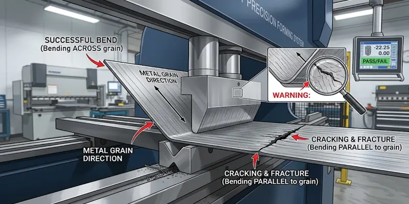
Rolled sheet carries a grain: the mill’s rolling process stretches the metallurgical structure and inclusions parallel to the rolling direction. Bend across the grain and the fibers being stretched lie across the bend line and resist tearing; bend with the grain, parallel to the rolling direction, and the stretch pulls the grains apart — which shows up as cracking on the outside bend radius. Bending with the grain also takes less force, which is part of why it survives unnoticed in shops — nothing about the setup feels wrong until the outer surface starts to split.
How to identify it:
- Parts nested in one orientation crack more often than parts nested the other way.
- Cracking persists even though the radius looks reasonable on paper.
- The outer face shows a rough, grainy texture where the splits form.
How to fix it:
- Check the rolling direction before cutting blanks — from the mill’s markings, the documentation, or the visible rolling lines on the sheet.
- Nest so the bend line runs perpendicular to the rolling direction wherever the part geometry allows, and flag grain direction at the nesting stage so it is a decision, not an accident of layout.
- When the design forces a with-grain bend, increase the inside radius — forming with the grain requires a larger minimum radius than forming across it.
- Test-bend critical materials in both orientations before committing a production nesting. The size of the grain effect is specific to the material and temper, not a fixed penalty you can apply blind.
Two cautions from the floor. Grain direction is not always easy to identify, and in some stainless it can be tough to define at all — if you cannot see the rolling direction confidently, two coupons cut from adjacent positions on the same sheet, one bent each way, settle the question faster than any datasheet. And for high-volume work, grain orientation belongs in nesting and material-utilization planning, so you do not discover the problem only after hundreds of blanks are cut.
Grain direction also shows up in a different defect — parts from the same batch forming to different angles — which is covered in detail in our article on batch-to-batch angle variation. Here the concern is only the crack.
Cause 3: The Grade or Temper Cannot Accept the Bend

Two sheets of identical thickness can behave completely differently, because grade, heat treatment, temper, and manufacturing history all set the ductility the metal brings to the bend. Annealed 6061-O aluminum bends where 6061-T6 cracks; high-strength steels need more generous radii than mild steel at the same thickness. The hard temper gives you the strength you ordered and takes away the formability you assumed.
How to identify it:
- Cracking appears with one material batch but not another under identical settings.
- The radius, grain direction, and edge condition all check out, and parts still crack.
- The material on the rack does not match the purchasing specification, or the certificate is missing.
- Cracking becomes more frequent as the stock gets harder or stronger.
How to fix it:
- Verify the grade and temper against the drawing and purchasing documentation — the label on the bundle is not a certificate.
- Check the mill certificate, including mechanical properties where available, and compare the current batch against the last one that bent cleanly.
- Ask the supplier for the recommended minimum bend radius for the exact condition you received, not the generic grade table.
- If the design permits, move to a more formable grade or a softer temper. For aluminum, forming in a softer condition and heat-treating afterward is the classic route where the process allows it.
Do not assume that material labeled aluminum, stainless, or carbon steel bends the same across grades and conditions — and if a job that ran clean for months starts cracking after a supplier or lot change, the material is the first suspect, not the machine.
Cause 4: The Crack Starts at a Cut Edge

This is the cause shops overlook most, because the edge looks fine at arm’s length. Thermal cutting processes — laser and flame — harden the edges and produce stress concentrations along the cut line; a laser edge also carries dross and a hard re-cast layer, worst at the sheet ends where parameters drift. Shearing and punching leave their own liabilities: burrs and microfractures along the cut. The outside of the bend is the tension side, and a crack needs a starting point — a hardened, dross-covered, or burred edge sitting there hands the crack exactly that. The signature from the checklist is unmistakable: a split that starts at the cut edge and runs into the bend, rather than one that opens mid-radius.
How to identify it:
- Cracks start from a particular edge rather than appearing uniformly along the radius.
- The crack location corresponds to a visible burr, dross line, or surface defect.
- Parts cut by different processes, or from different nests, show different cracking rates.
How to fix it:
- Put the burr side on the inside of the bend. The inside is in compression; the burr that would seed a crack on the tension side is mostly harmless there. This is a loading habit, not a capital purchase.
- Deburr and dress edges that land on the outside of a bend. Dressing sheared edges and surfaces helps remove the microfractures in critical areas, and a light edge break along the bend line removes the brittle skin and micro-notches a thermal cut leaves behind.
- Improve the cutting process where it is the source. Correct laser focus and cutting parameters at the sheet ends; inspect punched and sheared edges for micro-cracks before they become crack starters.
- Check the edge under magnification before blaming the material. Dross, a ragged laser underside, or a heavy shear burr is visible once you look for it.
- For heavy plate bent to tight radii, dressing may not be enough. Preheating between 200 and 300 degrees F before bending — applied particularly at thicknesses of 0.75 inch and greater — improves formability in the edge zone. Heat uniformly if you use it. This is a plate-shop measure, not a sheet-metal one.
Edge quality is not uniform along a cut, which is why edge-started cracks often appear on some parts and not others in the same batch. If the crack count per bundle tracks with which laser nest or shear blade the blanks came from, you have confirmed this cause without bending another coupon. For critical components, treat edge preparation as part of the bending process, not an optional finishing step.
Cause 5: Holes, Slots and Notches Inside the Deformation Zone
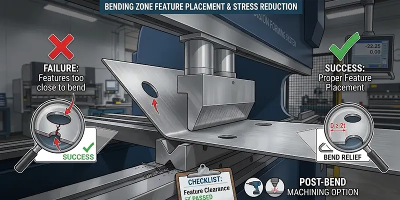
The bend zone is not just the radius. The material stretches across a deformation zone extending some distance on either side of the bend line, and any feature inside that zone sees the strain: a hole too close distorts toward an oval, a slot or notch corner concentrates stress and tears. The scrap ticket often reads “cracking at the bend” even though the bend geometry was never the problem.
How to identify it:
- Cracks occur near a punched hole, notch, or cutout rather than along the main radius.
- Holes near bends come out oval or shifted.
- The tear starts at a sharp internal corner of a cutout.
How to fix it:
- Keep hole edges at least two times the material thickness away from the start of the bend radius — the measurement is to where the radius begins, not to the bend line on the print, a guideline one fabricator applies specifically to minimize hole distortion near bends. Many shops use a more generous figure for slots, large cutouts, and less ductile materials, because the strain field is wider than the guideline minimum.
- Add a bend relief where a bend terminates at an edge or meets a cutout, so deformation ends cleanly instead of tearing. A common minimum relief is material thickness plus the inside bend radius, and cutting the relief with curves instead of sharp inside corners also reduces crack propagation in parts that see vibration in service.
- Drill, laser, or machine the feature after bending when it must sit close — the hole no longer participates in the forming strain.
- Relieve the corners of nearby cutouts so any tear that starts has nowhere to propagate.
This cause is decided at the drawing stage, which makes it the cheapest to fix and the most frustrating to discover — it usually surfaces after material and tooling are committed, sometimes at first-article inspection, on parts that are otherwise perfect.
Cause 6: Tooling and Method Choices That Add Strain

Even with the right radius, grain, and edges, the tooling combination and the forming method can push a marginal part over the line.
The V-die opening sets the strain field. For air bending, the common starting point is a V opening of six to eight times the material thickness — the lower end for tighter radii on forgiving material, the upper end for stability on thick or high-strength sheet, and wider for plate. A narrow V produces a smaller radius and less springback, but it concentrates the strain: tonnage rises and cracking risk rises with it. When a job is cracking, a wider opening within that range is often more forgiving than chasing the angle with a tighter setup. The opening also has to respect minimum flange length, required bending force, machine and tooling load limits, and part interference — not the radius alone.
Air bending forgives; bottoming and coining do not. In air bending the sheet rests on the die shoulders and the radius forms freely. In bottoming the punch drives the plate entirely against the die, and coining goes further, deliberately pushing the material to flow into the tooling geometry. That contact multiplies the stress on the outer fiber — the tonnage demand rises substantially, and the exact factor depends on the part, material, and tooling, so it must be calculated and checked against the machine rating, the tooling load limit, and the tool-holder limits rather than quoted from a rule of thumb. If a part cracks in bottoming and the tolerance allows air bending, switching method lowers the strain; the trade is a larger radius and springback you have to manage.
Worn tooling adds strain quietly. A punch nose worn round or galled, die shoulders with built-up metal or burrs, a V that has distorted — each changes the local geometry, concentrates strain in narrow zones, and drags the outer surface as it forms. Inspect the punch nose radius and working surfaces, check the die shoulders, and verify punch-die alignment; visible tool marks around the cracked region are a giveaway. Tooling selection and care is a discipline of its own, and our tooling and storage solutions page covers matching tools to material and method, inspection routines, and keeping spare sets conditioned so a worn set never gets pressed into service on a marginal job.
The punch nose radius matters too. A punch far sharper than the intended inside radius forces the outer fiber around a tighter curve than the part nominally calls for. Match the punch tip to the material and the target radius — do not force a sharp punch into a thick, high-strength blank. For unusual profiles or demanding materials, purpose-selected tooling beats forcing a standard set to perform an unsuitable operation.
Worked Example: Hairline Cracks on Laser-Cut 3 mm Brackets
A shop runs 3 mm mild steel mounting brackets, laser-cut blanks, inside radius specified at 3 mm on the print, bent on an 88-degree die in air bending. First articles are clean. Through the first production bundle, short hairline splits appear on the outside of the bend — on some parts, not all. The scrap bin grows; the program has not changed since setup.
Here is the sequence that finds the cause without bending a stack of test parts:
- Read the cracks. They start at the cut edge — specifically along the lower edge of the blank, where a laser leaves the dross and the hardest re-cast layer — and run into the bend. Mid-radius surface, away from the edge, is clean. That signature points at edge condition, not at the radius.
- Count the affected parts against their origin. The cracked parts cluster in the bundles cut from the sheet end, where the laser head ran slightly off-focus at the end of each nesting cycle. Edge quality, not bend setup, is tracking the defect.
- Check the radius anyway, because it is one measurement. A formed part measures roughly 4.7 mm inside radius — formed from a 24 mm V-die — comfortably above the 3 mm print callout and above the one-times-thickness guideline for mild steel. Radius is not the constraint here.
- Check the orientation. The bend runs across the rolling direction on this nesting. Grain is not the suspect.
- Apply the edge fixes. Burrs were on the tension side; the blanks get deburred along the bend line with the burr side loaded to the inside of the bend, the laser focus table gets corrected for the end-of-nest drop, and the bend-line edges get a light dress on the worst bundles.
- Verify with adjacent coupons — two blanks cut from neighboring positions on the same sheet, bent back to back under identical settings — one as-cut, one deburred. The deburred coupon bends clean; the as-cut one shows the same hairline start. Cause confirmed, and the fix cost a deburring pass and a parameter edit, not a tooling change.
The lesson generalizes: the crack told the story from the start. Reading it first, and asking which parts crack and where their blanks came from, turned a “press brake cracking problem” into a cutting-parameter problem in under an hour.
Building Crack Prevention Into the Routine
Chasing one crack is triage; the durable fix is a routine that catches the causes before the first production stroke.
Verify material consistency between batches. Before production, confirm grade and temper, actual sheet thickness, mill certificates and mechanical properties, rolling direction, and surface and edge condition. When a new batch behaves differently, run controlled test bends before releasing the full order.
Test the process with coupons, not production parts. A useful procedure for any new material or design: confirm grade, temper, and thickness; prepare coupons with documented grain orientation; start from a suitable punch radius and V-die opening; form a test bend with the intended method; inspect the outside surface under good lighting; record the actual inside radius and final angle; repeat with an adjusted radius or orientation if cracking appears. One coupon per new coil or lot, bent under production settings, catches a formability surprise while it costs one part instead of fifty. For critical applications, use the inspection method and acceptance criteria the drawing or material specification calls for.
Make the prevention decisions upstream. Grain orientation in nesting, burr-side-in loading, bend-line edge deburring on stocks with a cracking history, bend reliefs designed in rather than added after scrap — none of this is exotic, and none of it requires a machine upgrade. Cracking is decided by material, geometry, and method choices made before the ram comes down, and the cheapest fixes are the ones made on the print and the nesting table.
Where the Machine and Tooling Fit In
Material properties and part geometry cause most bend cracks, but the press brake and tooling system still decide whether a good process repeats. A machine operated inside its capacity, with stable synchronization and consistent contact conditions, turns a diagnosed setting into a repeatable one; running beyond rated capacity, or on unsuitable tooling, creates unstable forming conditions that put both parts and people at risk. Our press brake range covers the machine configurations — CNC, hybrid servo, electric, tandem, and heavy-duty — and the crowning, backgauge, and control options that keep forming conditions consistent across the workpiece.
Two honest boundaries apply here. CNC control helps operators hold consistent parameters across batches, but it cannot compensate for an unsuitable minimum bend radius or a brittle material condition — the material and tooling must first be compatible with the required geometry. And when cracking persists after the material, radius, grain, edges, and method have all been checked, the answer is a structured engineering review of the drawing, the tooling geometry, the bending sequence, and the inspection results — not a machine replacement. Our technical support team does exactly that review: remote diagnostics, troubleshooting, and operator training, aimed at finding the actual source of the problem rather than selling equipment unnecessarily.
FAQ
Why does sheet metal crack on the outside of a bend?
The outside surface of a bend is stretched under tensile stress while the inside is compressed. If the required elongation exceeds the material’s ductility, microscopic fractures form on the outer surface and grow into visible cracks. A tight inside radius, an unfavorable grain direction, a hard temper, and poor edge quality are the common contributing factors.
How do I find the minimum bend radius for my material?
Ask the material supplier for the forming data on the exact grade and temper, and note whether the stated minimum assumes bending across or with the grain — with-grain bends need a larger radius. General starting points exist (about one times thickness for mild steel, more for stainless and hard-temper aluminum), but the supplier’s data for your specific material, confirmed by a test bend, governs production.
Why do laser-cut parts crack when the same material bends fine after shearing?
Laser and other thermal cutting processes harden the edge and leave stress concentrations, dross, and micro-notches along the cut — a ready-made crack starter sitting right on the tension side of the bend. Deburr and lightly dress the bend-line edge, load the burr side to the inside of the bend, and check the laser focus and cut quality at the sheet ends.
How far should a hole be from a bend line?
A widely used fabricator guideline is to keep hole edges at least two times the material thickness away from the start of the bend radius, with more generous spacing for slots, large cutouts, and less ductile materials. If a feature must sit closer, drill or cut it after bending, or add a bend relief so the deformation ends cleanly.
Can increasing bending pressure, or switching to bottoming, eliminate cracks?
No — both work against you. More force does not restore ductility or correct a radius that is too tight, and excessive pressure can worsen deformation while adding tooling and machine risk. Bottoming and coining drive the material fully against the die and raise the stress on the outer fiber substantially compared with air bending. If a part cracks, find the root cause first; if tolerance allows, air bending is the more forgiving method.
How can I tell whether cracking is caused by the material or the press brake?
Bend the same material on a verified tooling setup with a suitable radius, then compare results against another material batch or grain orientation. If the cracking follows the material, investigate grade, temper, and edge condition. If it follows a particular tooling setup or machine, inspect the punch nose, die shoulders, alignment, and forming method. In practice, most bend cracks trace to material and process choices made before the ram comes down — which is why the machine is the last suspect, not the first.