Ordering replacement punches or dies for a press brake is not as simple as matching their dimensions or appearance. European, American, and WILA New Standard tooling use different mounting and clamping interfaces, so a punch that looks similar may not fit securely, may not sit where the holder expects it, or may line up at one end of the bed and not the other.
That last failure is the expensive one, because the tool went in, the clamp closed, and nothing looks wrong until the parts do. Compatibility is decided in four places — the interface, the seat, the stack and the load — and only the first of them is about the shape of the tang.

1. Why Press Brake Tooling Compatibility Matters
Press brake tooling compatibility determines whether a punch, die, or adapter can be correctly installed, securely retained, and safely operated on a particular machine. It is not a single yes-or-no answer, which is why buying on the family name alone goes wrong so often.
- Unexpected procurement costs: replacement tooling arrives and cannot be installed without adapters or a change of clamping system.
- Longer setup times: operators spend the shift shimming and re-aligning instead of running parts.
- Inconsistent accuracy: the first part bends short at one end, or the angle drifts along the bed, and the search moves to the machine, the material and the control before anyone checks the tool.
- Reduced flexibility: tooling cannot be shared between press brakes, so every machine needs its own inventory.
- Safety: a punch that is not positively retained can shift or drop when the clamp is released — the failure mode that hurts people rather than parts.
The problem concentrates in a factory running machines from different makers, or bought years apart: an older press brake on American tooling and a newer CNC machine with European quick clamps bend similar parts, and their upper interfaces have nothing in common.
4 Key Checkpoints for Press Brake Tooling Compatibility
Compatibility has to be checked in this order, because each gate can only be judged once the one before it is settled.
| Gate | The question it answers | What failure looks like |
|---|---|---|
| Interface | Will the tang physically enter and be gripped by this clamp? | The tool does not load at all, or loads only when forced — the cheap, obvious failure |
| Seat | Does the tool locate off the surface the clamp was machined to reference? | It loads and clamps, then bends short on one end, drifts along the bed, or shifts under load |
| Stack | Do punch and die close inside the open height, and still reach the material? | Risers, shims, or a job that cannot be run on the machine at all |
| Load | Does the tool's rated tonnes per metre cover this bend at this station? | Tip deformation, mushroomed tangs, angle scatter — and in the worst case a tool that fails instead of bending |
Gates three and four get signed off in a hurry and surface three months later. Gate two is never tested, because the tool went in and the clamp closed, which looks like success. Catalogues tend to stop at gate one, since gate one can be answered from a photograph; gates two to four need the machine’s dimensions, the job’s tonnage and the tool’s own load data. A one-line compatibility answer is an answer at gate one.
The upper punch and lower die do not necessarily share an interface, so each side is checked separately: the punch against the ram and clamp, the die against the bed, rail or crowning system.
"Standard" Is a Market Convention, Not a Specification
The word standard in a tooling catalogue describes a market habit, not a published dimensional document. The system the industry calls New Standard was introduced in June 2000 and has become the benchmark description for a whole class of quick-change tooling; trade press in 2026 still calls it “WILA-style, Trumpf-style, Amada ATC, or LVD-style” (Sheet Metal Industries). Four names, one family, and no guarantee that a tool sold under one name fits a clamp sold under another — so “we run European tooling” has not yet said anything checkable against a drawing.
2. European Style Press Brake Tooling: Features and Compatibility
European-style tooling, commonly associated with the Promecam system, is the default on modern CNC press brakes: modular, widely available in segments, and compatible with manual, mechanical and hydraulic clamping.
How European Style Tooling Works
The upper tang is narrow, nominally about 13 mm, with a profile and safety-retention feature designed to engage the corresponding clamp. How it is held matters more than how wide it is: a clamping plate acts on the side of the tang and pushes the punch into position, rather than a clamp pulling the tool onto a machined shoulder.
The safety groove is not decoration. Insert the punch from the front and a spring-loaded lever or pin engages the groove, so the tool cannot drop out before the clamp is tight — on a long gooseneck punch, the difference between a two-person lift and a one-person insert. Lower tooling usually sits in a dedicated die holder or on a standardised base; a 60 mm die base is widely encountered, though other dimensions exist.

Main Advantages of European Style Tooling
Modular configuration. Segments let operators build the length a job needs instead of installing full-length tooling for every setup — for a job shop with short runs, a twenty-minute changeover instead of a two-hour one.
Flexible clamping. The same profile can be held by manual pressure plates, quick clamps or hydraulic clamping, so a workshop can move to quick-change without replacing the machine, provided the interface is genuinely the same profile.
Availability. Standard punches, V-dies, goosenecks and special profiles come from many suppliers, which keeps price and lead time workable.
Potential Limitations
Because the plate pushes rather than pulls, the condition of the plate, the tang face and the clamp body all feed straight into the finished angle. The family also has more seating interfaces than a self-seating precision system, so punch position may need checking after each change, and groove profiles, tang dimensions and die mounting vary between makers.
Choose European-style tooling when you need flexible segments, a wide choice of standard profiles and cost-conscious procurement, on manual or quick-change clamps, on an existing European-style machine.
3. American Style Press Brake Tooling: Features and Compatibility
American-style tooling was the first generation built for mechanical press brakes and is still made the same way: planed from long bars, often up to 40 ft, then cut into the segments a customer orders.
How American Style Tooling Works
A common American upper configuration uses a nominal 1/2-inch (12.7 mm) straight, rectangular tang. The machine’s tonnage is fed directly through the top of that tang, straight down the vertical axis of the tool to the point (The FABRICATOR). That geometry is why the family is at its best in coining and bottoming, where the tool sees high force and the part shape is defined by the die. It can air form, but not with the repeatability of precision-ground tooling without a great deal of trial and error.
Two consequences matter for compatibility, and neither appears on a features table.
Segments are matched at manufacture. Cutting a long planed bar releases internal stress and the pieces move. Segments from the same bar are meant to be installed in the order they were cut and facing the same way. Drop a segment from another set into a run and you introduce a height and alignment difference no shimming will explain, because the tool is not the problem — the pairing is.
The tang carries the load. Anything that reduces contact at the top of the tang — a burr, a hammered clamping face, a soft holder — changes the seat and the stress path at once.
Traditional American tooling should also be distinguished from WILA American Style tooling, which is precision-engineered on the same 0.5 in interface but not compatible with WILA New Standard.

Where American Tooling Stops Working
The difficulty appears when it meets a different clamping interface. A 12.7 mm tang should not go into a 13 mm European holder because the numbers look close: the smaller tang slides into the wider slot, feels right, and never reaches the surface the clamp was machined to reference. That is not a small version of a matching standard — it is a different standard that happens to fit through the same hole, and no amount of clamp pressure corrects it.
A Fourth Case: American Precision-Style
One newer variant breaks the neat three-way division. American precision-style tooling keeps the 0.5 in tang but is ground to precision tolerances and located by rare-earth magnets that pull the punch shoulders into flush contact with the holder face before the clamp engages. For a shop whose work has moved from heavy plate toward lighter, more varied parts, it is a useful middle path — and proof that the interface shape gets a tool through the door, not onto its reference.
Choose American-style tooling when you already run American machines, want to keep your inventory, mainly bend conventional work, and want better clamping without changing the machine.
4. WILA New Standard Tooling: Precision and Quick-Change Technology
WILA New Standard is a precision tooling and clamping system built around repeatable positioning and fast, consistent changes. Unlike arrangements that rely on the operator to place the tool, it uses designed reference and seating surfaces to place it.
How WILA New Standard Tooling Works
The interface uses a nominal 20 mm upper tang with a groove front and back. The operator pushes the punch up into a powered clamp, hears the click that says it is home, and the clamp grabs the V groove and pulls the tool onto its reference point. Because the tang sits on the tool’s centreline, force runs straight down the vertical axis as with American tooling — but the location now comes from a machined reference rather than a plate squeezing the tang sideways.
Retention is the other half of the design: the safety click lets tools be changed vertically without the risk of dropping them, which matters most at the moment everyone ignores — unclamping, when a heavy punch held only by friction decides whether it stays in the beam.
The machine side is the least forgiving part of this family. The clamp is a powered assembly with its own reference surfaces, load rating and requirement for clean, stable pressure; fit a New Standard tool to a holder never machined to its geometry and the click becomes a noise rather than a confirmation.

Main Advantages of WILA New Standard Tooling
Repeatable positioning. Reference surfaces establish position the same way every time — valuable for tight tolerances and for parts that pass through several bending operations.
Faster tool changes. Compatible quick-clamping systems release and lock without repeated tightening of individual fastening points, which is where high-mix production loses its hours.
Integration with production systems. Smart tooling connects the physical tool to digital production: depending on configuration, tool identification, inventory management and CNC data transfer remove manual data entry, and the system fits automated cells where setup repeatability is the precondition for unattended running.
Potential Limitations
WILA New Standard needs matching clamping interfaces. A conventional European or American punch cannot simply be installed in a New Standard holder, and upgrading an existing machine is usually more than buying punches and dies: expect holder replacement, intermediate adapters, hydraulic or pneumatic supply, beam mounting checks, tool height and centreline work, and CNC or tooling-data integration.
Choose WILA New Standard when you change tooling frequently, hold tight tolerances, run complex multi-station setups, and want repeatability that does not depend on the operator’s eye.
5. European vs. American vs. WILA Tooling: Key Differences Compared
| Feature | European Style | American Style | WILA New Standard |
|---|---|---|---|
| Common upper tang reference | Approx. 13 mm | Approx. 12.7 mm (1/2 in.) | Approx. 20 mm |
| Tang form | Offset, with safety groove | Straight, rectangular | Grooved front and back |
| How the tool is held | Pressure plate pushing the side of the tang | Wedge, clamp plate or set screws on the tang | Powered clamp pulling the tool onto a reference |
| How the tool is located | Plate pressure plus tang face | Tang top and holder slot | Machined reference, self-seating |
| Loading | Front loading; safety pin engages on insertion | Usually side or end, tool by tool | Vertical, with a click and a powered clamp |
| Retention when unclamped | Safety groove plus lever or pin | Depends on the clamp; a loose tool can drop | Safety click holds the tool until released |
| Strongest at | Air bending with repeatability, fast changeover | Coining, bottoming, heavy plate, simple profiles | High-mix work with fast, repeatable changeover |
| First sign of a mismatch | The grip: plate cannot reach or hold the tang | The seat: tool sits low or rocks, angle drifts | The clamp: tool clicks but never reaches its reference |
Note: these are general system characteristics, not universal manufacturing specifications. Actual dimensions, safety features and compatibility depend on the tooling manufacturer and the specific clamping configuration.
There is no universal winner. A shop that already runs one family should keep it unless there is a clear reason to move; the useful work is converting the outliers deliberately, not standardising for its own sake.
6. Are European, American, and WILA Tooling Interchangeable?
Not directly. The common mistakes come from assuming that similar tang widths, or similar-looking safety features, indicate a matching standard.
| Combination | Direct fit? | The route that works |
|---|---|---|
| European tooling → American machine | No | Engineered adapter bar, or a replacement upper clamp machined for the 13 mm tang |
| American tooling → European machine | No | Conversion holder or adapter, or a clamp built for the 0.5 in tang |
| European tooling → WILA New Standard machine | No | Dedicated adapter for the punch profile, or a New Standard-compatible retrofit clamp |
| WILA New Standard tooling → European machine | No | Compatible retrofit clamping system, or an engineered intermediate adapter |
In every case the adapter or clamp must provide correct retention, alignment and load transfer, and the stack and load rating have to be re-checked afterwards. The machine’s tonnage does not change, but what reaches the tool might. The one route that never works is force: a tool that has to be tapped or wedged into a holder is not compatible, it is damage waiting to happen.
An Important Distinction: WILA Is Not One Single Tooling Standard
WILA is a tooling manufacturer and technology provider, not another name for one universal interface — its range includes New Standard tooling and American-style tooling, among other solutions. So when a supplier says a machine supports WILA tooling, ask which WILA. That one question prevents a class of expensive purchasing mistakes.
7. How to Check Press Brake Tooling Compatibility Before Ordering
The checks below follow the four gates.
Step 1: Identify the Upper Punch Tang Profile
Check tang width and thickness, the complete profile, any safety groove or locking arrangement, shoulder and seating geometry, loading direction, and any maker’s identification. Do not measure only the width: the profile, the reference surface and the retention feature are what the clamp engages, and a dimensioned cross-section compared against the machine’s clamping specification is the only reliable identification.

Step 2: Inspect the Upper Clamping System
The clamp, not the tool, defines where “seated” is. Identify whether the machine uses mechanical clamps, European quick clamps, American precision clamps, hydraulic or pneumatic clamping, New Standard clamping or a proprietary arrangement. Then check whether it loads from the front, laterally or vertically — two clamps built for the same nominal tang can locate the tool on different surfaces.
Then look at condition, not just type. Clamp plates deflect around punch tangs, and set screws miss the tang entirely when their spacing does not match the tool; in both cases nobody on the floor knows whether the tool is clamped properly, or at all. Holder condition carries straight through to the part — as the trade press puts it, low-tolerance holders “can make a relatively good press brake appear to not work very well” (The FABRICATOR).
Step 3: Measure the Lower Die Holder
Check die base width against the holder or mounting groove, base profile, die height, V opening, centreline and load capacity. A die can be perfectly correct for the bend and wrong for the holder. That is what happens after a partial retrofit: the upper clamp is replaced to take a precision tang, the original die rail stays, and the lower tooling no longer sits as it did.

Step 4: Verify Working Height and Machine Clearance
Confirm punch height, die height, adapter height if applicable, open height, ram stroke, maximum and minimum closed height, and clearance for loading the part. Height is the most frequently overlooked part of a conversion, and it is the reason an adapter can turn a workable machine into one that cannot run a deep box (Section 9).
Step 5: Check Tonnage and Tooling Capacity
Verify the maximum allowable load per unit length for the punch, die, any adapter and the clamp, against machine tonnage and the bending force the material and bend length require. The weakest component in the load path sets the permissible capacity — and the rating for a given interface varies far more than most buyers expect (Section 8).

Step 6: Confirm Centreline Alignment
Incorrect positioning shows up as uneven angles, dimensional deviation, uneven loading, localised wear and stress on the clamping components. Check across the full working length, not at one point. Before blaming the tooling for an angle that drifts along the bed, rule out the bed: a die on an uncrowned bed bends a different angle mid-span than at the ends, and no tooling choice fixes that. Crowning compensation is a machine feature, specified with the machine.
Step 7: Request Written Compatibility Confirmation
Ask the supplier to confirm compatibility in writing, with the machine model and serial number, photographs of the existing clamps, tooling drawings and the required bending specifications. This matters most with older machines, customised holders and cross-brand conversions — the three situations where a catalogue answer and your machine are least likely to agree.
The Twenty-Minute Seat Check
Before blaming angle compensation or the control for a bend that varies, prove the seat. The procedure is old, cheap and unglamorous.
- Clean both faces. Dried oil or a chip reads as a dimensional error.
- Mark the reference surfaces lightly with marking compound or layout blue.
- Clamp and cycle once, without material, then release and read the contact pattern. Full, even transfer along the segment is a seat; a patchy or one-ended pattern is a tool on the wrong face or on a burr.
- Repeat left, centre and right. If the pattern changes, the holder or the ram is telling you something, not the tool.
- Pull-test the retention. With the clamp released, the tool should still be held by whatever retention the system provides. If it drops free, the safety feature is not engaging — the failure mode that hurts people, not parts.
Run it when new tooling arrives, and again whenever a job produces angle scatter no program change explains.
8. Load Rating: Why "European" Can Mean 100 or 300 Tonnes per Metre
This is the part of compatibility that no tang dimension tells you.
When a UK fabricator took delivery of a 600-tonne, 4-metre press brake, the published account noted that the specialist tooling bought with the machine lets the shop press 300 tonnes per metre, “unlike the standard Euro tooling which will only achieve 100 tonnes per metre” (Sheet Metal Industries). Same nominal interface family, three times the capacity, depending entirely on which tool is in the clamp.
- Rating is per metre and per tool, not per machine. A short segment carries the load of the station it serves, not a share of machine tonnage divided along the bed: a 100 mm punch in the middle of a 3 m bed still sees the whole force of that bend.
- Thin sections derate. Anything that reduces the cross-section at the neck — gooseneck and other relieved punches being the classic case — carries less load at the same height. Use the tool’s own tonnes-per-metre data, not the family’s reputation.
- Hardness buys wear resistance and costs toughness. Precision-ground tooling is hardened through the section and near the surface, which is what lets it hold an edge for years; the same treatment makes it less forgiving of overload than the softer, tougher planed tooling it replaced. Overloaded, a hard tool does not bend politely out of shape — it can fail suddenly, and the pieces leave at speed.
The Practical Test
Take the job, not the catalogue. For the heaviest bend you expect to run, calculate the forming tonnage, divide by the length of tooling actually under the bend, and compare the result with the tonnes-per-metre figure for that specific punch and die. If you cannot find the figure, you do not have a compatible tool — you have an unknown one.
9. Using Adapters to Convert Between Tooling Standards
An adapter can be far cheaper than replacing an inventory, but it is not a piece of metal joining two tang widths: it has to transfer bending load while holding position and retention, and it has to be designed around the actual geometry of both interfaces.
| Existing Machine Interface | Required Tooling | Potential Solution |
|---|---|---|
| European style | American style | Engineered upper and lower adapters |
| American style | European style | Matching conversion holders or adapters |
| European style | WILA New Standard | Compatible retrofit clamp or intermediate adapter |
| WILA New Standard | European style | Dedicated European tooling adapter |
| Custom interface | Standard tooling | Machine-specific engineered conversion |
These are possible approaches, not guaranteed combinations; each needs dimensional and load verification.
What Adapters Quietly Cost
A mating surface you did not have. Force now passes through ram, adapter, tool and die instead of ram, tool and die. Each extra joint is an opportunity for misalignment under load, and the errors stack rather than cancel.
Daylight. A block between ram and tool is thickness removed from open height and throat clearance. On flat work nobody notices; on a deep box with tall return flanges the lost clearance can decide whether the part comes out at all, at which point the setup saving is cancelled in the last thirty seconds of the run. If that is your job mix, a deep box bending guide is a better starting point than an adapter catalogue.
Its own rating and its own flex. The adapter is a structural component: material, fastening and contact surfaces have to suit the operation, and it can be the weakest link in a machine rated for far more. Some also need alignment at installation, which eats the productivity gain the quick-change system was bought for.
When an Adapter Is Worth Using
When the existing inventory represents a significant investment, only a few machines need converting, the working height can be preserved, the machine structure can carry the conversion, the total cost stays below replacing the library, and the required accuracy can still be held. For a long-term upgrade, replacing the clamping interface outright is sometimes the better investment than stacking adapters.
When the Answer Is a Retrofit Clamp, Not an Adapter
Replacing the upper clamp — and, if needed, the lower holder — so the machine accepts the family natively is engineering work rather than shopping, and it is the right answer more often than shops expect. What to settle before anyone quotes it:
| What to settle | Why it decides the outcome |
|---|---|
| Clamp body geometry and reference surface | The clamp, not the tool, defines where "seated" is |
| Actuation: manual, pneumatic or hydraulic | Whether the machine can drive it, and who maintains it |
| Rated clamping load per metre | A clamp can be rated below the jobs the machine was bought for |
| Daylight consumed | Even a flush-mounted clamp changes the stack |
| Adjustment axes | Front-to-back and parallelism decide whether bed deflection can be corrected afterwards |
| Retention feature | The hook, groove or click that keeps a released tool in the beam |
| Control-side changes | Tool library, heights, and any tonnage or clamping interlocks |
A retrofit is where “can I use this tooling?” becomes “what is this machine now?” — a legitimate question for the machine builder rather than a tooling catalogue. CAMT builds tooling clamping systems as retrofit kits, with adapter bars for European, Amada, WILA and Trumpf geometries, because most machines we are asked about arrive with a tooling library already in the building.
10. Should You Upgrade to a WILA-Compatible Quick-Clamping System?
Many workshops consider replacing conventional manual clamping when volumes rise or changeovers multiply. A quick-clamping system reduces setup work and operator effort, but the investment should follow production requirements rather than the reverse.
| Comparison | Conventional Manual Clamping | Quick-Clamping System |
|---|---|---|
| Tool installation | Manual fastening and adjustment | Faster locking and release |
| Changeover time | Generally longer | Generally shorter |
| Operator workload | More manual handling | Reduced manual fastening |
| Repeatability | Depends on seating and adjustment | Improved with compatible precision seating |
| Automation integration | More limited | Available with hydraulic or pneumatic actuation |
| Initial investment | Generally lower | Higher |
| Best application | Infrequent tool changes | Frequent changes and production flexibility |
Before purchasing, settle how many complete tool changes you perform per shift, whether existing punches and dies can be retained, and whether the ram and bed accept the new clamp. Then confirm what accuracy the work actually needs, whether the system must integrate hydraulically, pneumatically or through the CNC, and what retention and protection the operator gets during a change.
One caution: a quick-change clamp is not automatically faster if the library is not organised around it. Six segments hunted out of an unlabelled rack cost more minutes than the clamp saves.
11. How to Choose the Right Tooling System for a New Press Brake
Tooling compatibility belongs in the specification discussion, not the delivery conversation. Many buyers compare tonnage, bending length, CNC axes and price while overlooking the interface, then discover the cost when the machine lands and the existing tooling cannot be used.
If you already own a substantial collection of punches and dies, keeping that standard is usually the most economical option: an interface you can order is cheaper than a library you have to rebuild.
| Production Type | Important Tooling Considerations |
|---|---|
| General fabrication | Standard tooling availability and flexibility |
| High-mix, low-volume production | Segmented tooling and quick changeovers |
| Heavy plate bending | Tonnage capacity, tool rigidity, load distribution |
| Precision enclosure manufacturing | Centreline alignment and repeatable tool positioning |
| Automated bending | Quick clamping, tooling data, automation integration |
| Long workpiece production | Tool straightness, alignment, crowning compatibility |
If you plan to run several CNC press brakes, standardising interfaces simplifies inventory, training, procurement and scheduling — but only after confirming the machines share the same actual interface. The same family name on two machines from different decades is not evidence of that.
Put Eight Items in the Enquiry
The cheapest moment to fix an interface is while the machine is still a specification; once the frame is welded, the clamp is what it is. These eight belong on the purchase order, whether you are buying a machine, a clamp or a set of punches:
- The interface by name and by drawing — European/Promecam, American, New Standard/WILA-style or proprietary, with a dimensioned tang section.
- The reference surface — the face the clamp locates on, stated rather than assumed.
- Punch height and die height as a pair, against open height and stroke.
- Die base width and height, and the rail or crowning arrangement it must sit in.
- Rated tonnes per metre, for the tools and for any clamp or adapter in the stack.
- Retention method — groove, click, hook or magnet — and what holds a released tool.
- Actuation and its supply — manual, pneumatic or hydraulic, and where the pressure comes from.
- The heaviest job the machine will ever run, in tonnes per metre at the tool, not in machine tonnage.
Anyone who can answer all eight in writing is selling you a system. Anyone who answers the first and moves to price is selling you a box.
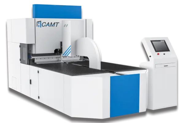
CAMT builds CNC press brakes with configurable specifications, so the interface is a specification item rather than an afterthought. Explore the CNC press brake range to discuss a configuration that matches your production and your existing tooling.
12. How CAMT Helps Solve Press Brake Tooling Compatibility Problems
Choosing the right press brake is only part of building an efficient bending operation. The tooling, the clamping system, the machine structure and the production requirement have to work together.
Customised tooling clamping systems. CAMT supplies clamping configurations in manual, hydraulic, pneumatic and customised form. Depending on the machine and interface, solutions can be developed for European, Amada-style, WILA-style and other specialised profiles, and for existing machines, engineered intermediate adapters and retrofit arrangements can replace major modification. Feasibility is confirmed against beam dimensions, mounting points, required load capacity and available space.
WILA-compatible hydraulic clamping and smart tooling. For shops seeking better tool-change efficiency, WILA-compatible hydraulic clamping can include hydraulic tool clamping, precision alignment adjustment, compatible segmented tooling, safety retention and machine-specific retrofit components. For advanced environments, WILA smart tooling carries the tool’s own data, so geometry, V opening and load information reach the control without being typed in — removing the manual entry step where most “the tooling does not fit” errors actually begin.
Storage, support and upgrades. Compatibility is only part of tooling management; storage and handling decide whether the clamp’s speed advantage survives contact with the shift. If you are unsure whether an existing machine can take a different standard, our engineering team can evaluate it through CAMT technical support.
Not every shop should switch families. A new interface is a machine project with a tooling bill attached, not a tooling purchase: high-mix work with six changeovers a shift usually pays for it, a heavy-plate coining shop usually does not. The engineering exists to answer that question for a specific shop, not to make one family win.
Need help checking whether your existing tooling will fit a new CAMT press brake or a retrofit clamp? Send your machine model, tooling photographs and dimensional drawings, and our team will review the configuration and recommend a solution. The wider picture — profiles, V-opening selection, tonnage limits and maintenance — sits in the press brake tooling guide, which is the better place to start if your question is what to buy rather than what will fit.
13. Press Brake Tooling Compatibility Checklist Before Purchasing
| Inspection Item | Information Required | Confirmed |
|---|---|---|
| Machine identification | Manufacturer, model, serial number | ☐ |
| Upper tooling standard | European, American, WILA New Standard, custom | ☐ |
| Punch tang | Width, thickness and complete profile | ☐ |
| Safety retention | Groove, click, button or locking arrangement | ☐ |
| Upper clamp | Manual, mechanical, hydraulic or pneumatic; loading direction | ☐ |
| Reference surface | Which face the clamp locates the tool on | ☐ |
| Lower die | Base width and mounting profile | ☐ |
| Tool height | Punch and die heights as a pair | ☐ |
| Machine clearance | Open height, stroke, closed heights | ☐ |
| Centreline alignment | Upper and lower tooling reference | ☐ |
| Load capacity | Punch, die, clamp, adapter and machine ratings | ☐ |
| Heaviest job | Tonnes per metre at the tool, and tooling length under the bend | ☐ |
| Adapter requirements | Upper and lower conversion components | ☐ |
| Segmentation | Tool lengths, and whether segments are a matched set | ☐ |
| Documentation | Drawings and written compatibility confirmation | ☐ |
If a critical measurement is unknown, do not order on the family name alone. Where there is no drawing at all — a used machine and a box of unmarked tooling — photograph the tang beside a rule in the same frame so the proportions survive the email, and record the dimensions. Send them to the machine builder and to two tooling suppliers; if the independent answers agree, you have a working identification. What no amount of measuring establishes is the load rating, so treat any tool of unknown origin as unrated until someone states a tonnes-per-metre figure for it. Organising that library as you go is a separate job, and tooling storage solutions make the next changeover cheaper.
Final Considerations
European, American and WILA New Standard tooling each serve different machine configurations and production requirements. The decision is not which standard looks most advanced, but whether the punch, die, clamping system and press brake work together safely, accurately and at the tonnage the job demands.
Before buying replacement tooling or converting an existing machine, verify the mounting geometry, the reference surface, working height, centreline, load capacity and adapter requirements — in that order, and in writing. If you are planning a new press brake purchase or a tooling-system upgrade, contact CAMT with your machine specifications and production requirements.