When a press brake starts producing bad parts, the fastest route to a fix is a shorter list of causes, not a longer one. Every bending defect leaves a signature: where it appears on the part, when it appears in the run, and whether it repeats. Read the signature correctly and a five-minute program correction stays a five-minute fix. Read it wrongly and you spend an afternoon chasing a machine fault that was really a change in the material.
This guide works the way an experienced setter does: read the defect’s signature, run a four-check isolation sequence from the cheapest check to the most expensive, then fix the layer the evidence points to. It covers seven defect families, part-to-tool collisions, and the machine-side faults that show up as bending defects first.
At a glance
- Angle open in the middle of a long bend: usually deflection, fixed with crowning rather than more angle correction.
- Angle differs from left to right: usually a tool that is not seated, uneven wear, or Y1/Y2 out of parallel.
- Same wrong angle on every part: usually wrong program data or springback allowance, not the machine.
- Parts disagree within one batch: usually material variation or backgauge repeatability. The mill’s tolerance zone is wider than most people assume.
- Wrong flange dimensions: backgauge reference, mechanical play, or the part moving during the bend.
- Cracking at the bend line: inside radius, grain direction and edge condition, all decided before the first bend.
- Marks, scratches and galling: die condition and sheet handling.
- Sync errors, oil temperature, drifting axes: these appear as bending defects first. The fix belongs to maintenance, not to the bend program.
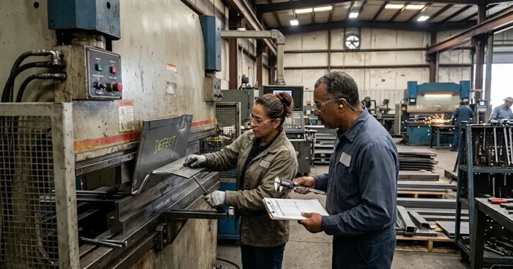
Start Here: Read the Defect Signature
Before touching the controller, classify what you are seeing. Two questions cut the possibilities fastest: where on the part does the defect appear, and does it repeat identically from part to part? A defect that repeats identically points to a deterministic cause: the program, the tooling geometry or the machine geometry. A defect that wanders points to something variable: material, temperature or a wearing component.
| Defect signature | What it usually means | First check | Most likely fix layer |
|---|---|---|---|
| Angle more open in the middle of a long bend, ends correct (the “canoe”) | Ram and bed deflection under load | Is the part long or the job high-tonnage? Bend a short part at the center | Crowning, not angle correction |
| Angle differs from left to right | Tool not seated, uneven wear, or Y1/Y2 out of parallel | Reseat the tooling; flip the part end for end | Setup, then machine |
| Same wrong angle on every part, uniform along the bend | Springback allowance or program data wrong for the material loaded | Verify material, thickness and tool data against the program | Program / springback table |
| Angles wander from part to part, no pattern | Material variation inside mill tolerance, temperature, or backgauge repeatability | Micrometer a sample of sheets; test backgauge repeat | Material / backgauge |
| Flange dimension wrong or drifting during the run | Backgauge reference, mechanical play, blank size, or part handling | Measure the blank; re-home and test the backgauge | Backgauge / handling |
| Cracks at the bend line | Inside radius too tight, bend parallel to grain, burrs on the outside of the bend | Compare radius with material minimum; check grain direction | Tooling selection / part design |
| Marks, scratches or galling on the outer face | Die shoulder condition, chips, sharp die edge, sheet dragging | Inspect and clean the die under good light | Tooling condition / handling |
| Part strikes the tool or cannot be removed | Interference in geometry or bend sequence | Walk through the sequence stage by stage | Tooling and sequence |
Two cheap tests that narrow it down
- Test strips. Cut strips from the same sheet and bend them at the left end, center and right end of the bed. If the error stays with a position, suspect tooling or the machine. If it follows the strip, suspect the material.
- Flip the part. Rotate a full-length part end for end and bend it again. If the error stays on the same side of the machine, the cause is in the machine or tooling. If it moves with the part, the cause is in the material.
The Four-Check Isolation Sequence
When the signature alone does not settle it, isolate the cause layer by layer. The order matters because each check either clears a whole category or hands you the culprit.
Check 1: The Program and the Setup Sheet

Confirm that what the controller thinks is happening matches what is physically in the machine. A surprising share of “defects” are programs built for a different job: the wrong material type selected, a thickness typed in nominal instead of measured, or a tool file left from the previous run. Verify the punch, the die, the material callout and the angle target against the setup sheet before changing any parameter. If the previous job used the same die, confirm the tool is seated the same way. A tool that is not fully seated changes the effective die height and, with it, every angle in the program.
Check 2: The Material

Measure, do not assume. Take a micrometer to three or four sheets from the current batch, at the ends as well as the middle of each, and compare against the program. Material that meets specification still varies: a 16-gauge sheet can be anywhere from 0.053 to 0.067 in. thick and still be called 16-gauge (The Fabricator). If the batch is laser- or plasma-cut, remember that the heat-affected zone along the cut edge can harden the material locally, so a bend line that crosses cut edges may not form like the rest of the sheet.
Check 3: The Tooling
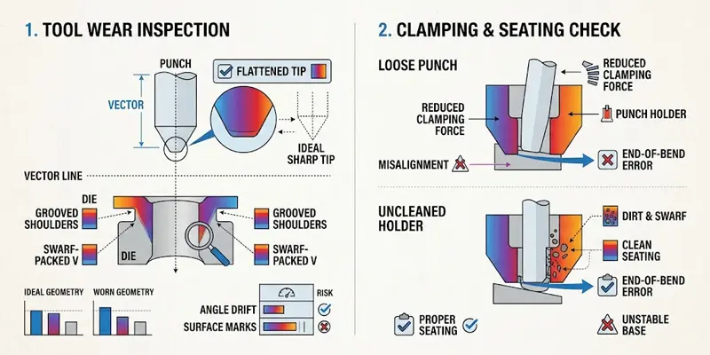
Pull the punch and die and look at them under good light. A flattened punch tip, grooved die shoulders or swarf packed into the V changes the bending geometry silently. Wear on the die shoulder radius is the classic hidden cause of both angle drift and surface marks. While the tooling is out, check the clamping: a punch that has worked loose, or a holder that was not cleaned before seating, produces end-of-bend errors that look exactly like machine problems.
Check 4: The Machine Geometry

Only after the first three checks come back clean does the machine become the suspect. The usual suspects are ram-to-bed parallelism under load (deflection, covered next), Y1/Y2 synchronization between the two cylinders, hydraulic condition, and backgauge repeatability. A healthy machine holds the two ends of the ram within a very small tolerance, and your manual gives the figure for your model. If the two ends disagree by more than that, the fault is real and mechanical: seals, valves or position feedback. Editing the bend program will not fix it. The machine-side table later in this guide lists what to look for.
Angle Varies Along the Bend Length: Deflection and Crowning
This is the most misdiagnosed defect on any long press brake. The part comes off with the ends at target and the middle open, and the setter adds angle correction, which fixes the middle and ruins the ends.
The cause is physics, not error. Under load the ram and bed bow apart between the cylinders, so the punch penetrates less in the middle than at the ends and the center angle comes out larger. The effect grows with bend length and with tonnage per meter. The Fabricator notes that crowning is generally used on press brakes of roughly 80 tons and 8 feet and up, and can be applied to smaller machines depending on table length and application (The Fabricator).
What to do, in order:
- Confirm the signature. Deflection errors are tied to the center of the machine, not to a part. Bend a short part in the center of the bed. If it comes out on angle while long parts canoe, you are looking at deflection.
- Check the crowning setting. On machines with CNC wedge or hydraulic crowning, the compensation is calculated from sheet thickness, length, die opening and tensile strength, so a wrong material in the controller produces a wrong crowning value. This is why Check 1 comes first.
- Make sure the crowning mechanism moves freely. A seized or unlubricated wedge cannot compensate, however it is set.
- Rule out worn tooling and thickness variation across the sheet. Both produce the same symptom.
- Reduce the load if the job allows. A wider V opening lowers the force per meter.
- Without powered crowning, shimming or adjusting the dies is the traditional fix. It works, but it is slow and specific to each setup.
If long, tight-tolerance parts are routine rather than occasional, crowning stops being optional. See our press brake crowning systems page for how mechanical and motorized types differ, and the press brake range to compare machines.
Takeaway: crowning corrects deflection. It cannot correct worn tooling or inconsistent material, so rule those out first.
Angle Differs From Left to Right

One end of the bend is more open than the other, a rectangular part comes out tapered, or a box will not sit square.
Why it happens. The common causes are a tool that is not fully seated in its clamp, uneven wear along the tooling, a ram that is not parallel to the bed (Y1 and Y2 out of step), and loading the part off-center so one side of the machine carries more force.
How to confirm it. Measure the angle at both ends of a full-length bend, then use the flip test above. If the error stays on the same side of the machine, the cause is in the machine or the tooling.
Fixes.
- Remove, clean and reseat the punch and die, making sure each sits fully in its holder.
- Look for damaged or worn sections and replace them.
- Center the workpiece in the bend zone where possible.
- If the error stays with the machine, have a qualified technician check Y1/Y2 position feedback and synchronization. Our maintenance and upgrades page explains what we can help with.
Takeaway: flip the part before touching the machine. It tells you at once whether you are chasing a machine problem or a material problem.
Same Wrong Angle on Every Part: Springback and Program Data
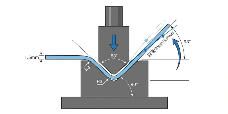
Springback is the metal recovering elastically as the load comes off. Every metal does it and no setup avoids it. As a starting point, air-bent mild steel opens a degree or two past the formed angle, and stainless and high-strength steels open noticeably more. A consistent offset also appears when the control holds the wrong material, thickness or tool, because the calculated stroke depth is wrong from the start. The compensation is a deliberate overbend, entered as an angle correction or handled by a springback table keyed to the material.
How to confirm it. Compare measured and programmed angles on several parts. A consistent offset is springback or setup data. Then check that the material, thickness, V opening and punch radius in the program match the real setup. A common mistake is running stainless steel on a mild steel setting.
Four practical points keep springback from eating your day:
- Compensation depends on the forming method. In air bending, the inside radius floats at about 16% of the die opening for 60-ksi mild steel, and a floated radius springs back far more than one bottomed into the die. Bottoming makes the angle much less sensitive to variation in thickness, grain and yield strength, but it takes far more force and can damage the machine and tooling if done wrongly. Two machines in one shop forming the same part, one air bending and one bottoming, will not agree perfectly, and neither is wrong (The Fabricator).
- Choose the V opening deliberately. For air bending mild steel, start at six to eight times the material thickness: six for tighter radii on forgiving material, eight for stability on thick or high-strength sheet, and wider for thick plate. A narrower V gives a smaller radius and less springback, but a given ram-depth error then moves the angle more, tonnage rises and cracking risk rises. If a job is fighting you, a wider opening within that range is often more forgiving than more angle correction.
- Verify on scrap from the same batch. Springback tables assume average material. Test-bend, measure with a protractor or the machine’s angle measurement, adjust once, then start the run.
- Save the correction. Store it by material, thickness and tool in the control’s library so it is not rediscovered on the next job. On machines with laser or contact measurement, the controller closes this loop automatically. See the bending angle measurement page.
Takeaway: a constant error is a data problem. A varying error is a process problem.
Parts Disagree Within One Batch: Material Variation

When every part is wrong in a different way, the program is usually innocent. Deterministic causes produce identical results, so the variable is almost always the material, and the scale of the variation surprises people who have only read nominal spec sheets.
The numbers are worth knowing. A36 averages about 60,000 psi tensile strength, but its tolerance zone runs from roughly 55,000 to nearly 80,000 psi . A 16-gauge sheet can be anywhere from 0.053 to 0.067 in. thick and still meet specification. Sheet sold as A36 can also average well above the 36,000 psi minimum yield (The Fabricator). Each of these in-tolerance variations changes the formed angle, especially in air bending.
Work the batch in this order:
- Measure thickness across the batch, at the ends and middle of several sheets. Sort the thicker or stiffer sheets and see whether the angle tracks the measurement.
- Check grain direction. Bending with, against or across the rolling direction forms differently. If the blanks were nested differently from the last batch, the grain moved with them.
- Look at the cut edges. Laser and plasma cutting can harden the heat-affected zone, so bend lines that cross cut edges form harder than bare mill edge.
- Check handling and warm-up. Inconsistent positioning against the backgauge, oil or protective film on the sheet, and a machine that has not warmed up can each add scatter. A consistent warm-up routine before first-article approval removes one variable.
- Re-run the springback test on the current batch, not on leftover sheet from the last order.
None of this means the material is bad. It means the process has to absorb the tolerance zone, not the nominal value. That is the gap that in-process angle measurement and adaptive crowning are built to close: a bending angle measurement system measures the angle during the bend and corrects the stroke automatically.
Takeaway: if you cannot control the material, measure the result and correct it during the bend.
Flange Dimensions Are Wrong: Backgauge Causes
When angles are fine but flange lengths are not, the bend is innocent and the part is being gauged differently than you think. Before blaming the backgauge, measure the blank: a cutting error looks identical to a gauging error until you check. Then look at three causes:
- Reference shift. The backgauge lost its home position after a collision, a power cycle or a program change. Re-home it and re-run the first article before touching anything else.
- Mechanical play. Worn ball screws, loose fingers or debris on the rails produce drift that grows over a run. The tell is a flange dimension creeping in one direction as the batch progresses. Check finger tightness and rail cleanliness. Recurring drift is a maintenance item, not a setup item.
- Part handling. On long or heavy sheets the part can lift or rock off the gauge edge during the bend. The dimension error is real but the backgauge is innocent. Front supports or a follower system hold the sheet against the gauging surface through the stroke. See bending follower supports.
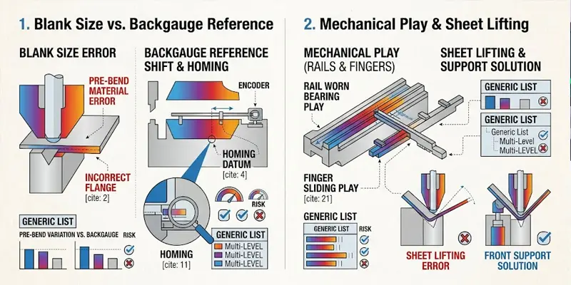
Two further causes are easy to miss. Bend deduction values that do not match the real material and tooling shift every flange, so re-measure test parts and update the values instead of relying on defaults. And on multi-bend parts a small error on each bend adds up, so the last flange can be badly off even when each bend is nearly right.
Verify repeatability with a simple test: run ten gauging cycles and indicate the stop position. On a healthy system the result repeats within a few hundredths of a millimeter, and your manual gives the figure for your model. Anything worse needs attention before the next production run. Recalibrate after any collision, tool change or repair. The backgauge system selection page covers axis configurations and what each axis contributes on complex parts.
Takeaway: measure the blank, not just the bent part.
Cracking at the Bend Line
Cracking is almost always decided before the first bend, by the relationship between inside radius, V opening, grain direction and the material’s ductility. Work through it in this order:
- Compare the inside radius with the material minimum. Every alloy and temper has a minimum bend radius below which the outer surface exceeds its elongation limit. Soft grades tolerate tight radii. Harder tempers, such as 6061-T6 aluminum, high-strength steel and some stainless grades, need much larger ones. If the print demands a radius tighter than the supplier’s data allows, the fix is a design conversation, not a machine adjustment.
- Check the V opening. A V narrower than about six times the thickness multiplies the strain at the outer fiber. For thick plate and high-strength material, use the wide end of the range: eight times the thickness and beyond.
- Check grain direction. Bends parallel to the rolling direction crack sooner than bends across it. Rotate the blank so the bend line runs across the grain whenever the part allows.
- Check the cut edge. Put the burr side on the inside of the bend and deburr. Laser-cut edges can harden the bend line (see the material section).
- Check temperature and temper. Cold sheet in a winter workshop has less ductility, so a part that bent fine in July and cracks in January is no mystery. A softer temper, or annealing where the process allows, is sometimes the answer.
Takeaway: cracking is usually decided before the metal reaches the press brake.
Die Marks, Scratches and Galling
Surface defects do not cost angle tolerance, but on visible and pre-finished parts they cost scrap just the same. The cause ladder is short:
- Dirty or grooved die shoulders. The shoulders carry every part’s outer surface across them. Embedded swarf prints onto the sheet, and a grooved shoulder scores a line down every bend. Clean and inspect first; this resolves most complaints.
- Too-sharp die edge radius. A crisp shoulder bites into the surface. Polish the shoulder, or use a die with a larger shoulder radius.
- Chips from cutting. Laser and plasma blanks carry dross and chips into the die. Wipe the sheet before bending.
- A V opening that is too narrow for the thickness raises contact pressure and can dent the surface.
- Sheet dragging. Large flanges can drag across the die as the part rises. Follower supports move with the sheet and prevent it.
- Materials that mark easily. Pre-finished, brushed and polished parts justify urethane pads, nylon or polyurethane insert dies, or protective film.
One habit prevents the whole family: inspect and wipe tooling at every setup, and store it properly (see our tooling and tool storage solutions). If marks appear mid-run rather than at the start, suspect chips or debris in the clamp, not the die you cleaned. If a mark repeats in the same place on every part, the tool is damaged. If it moves around, look at the sheet and the handling.
Takeaway: the same place on every part means fix the tool; wandering marks mean look at the sheet and the handling.
When the Part Collides With the Tooling
Some defects are not about the bend at all. A deep box or a part with return flanges can strike the punch, holder or clamp partway through the sequence, or become impossible to remove after the final bend. A gooseneck punch, a different bend order and offline simulation usually resolve it. We cover this in How to Bend Deep Boxes and Cabinets Without Tooling Interference.
Machine-Side Causes to Check After the Basics
If program, material and tooling all check out, look at the machine. These checks need a qualified technician and, where relevant, the manufacturer’s manual.
| Area | What can go wrong | What it looks like |
|---|---|---|
| Y1/Y2 synchronization | Position feedback or valve problems let the ram run out of parallel | Left-to-right angle difference; synchronization errors on the control |
| Hydraulic oil | Wrong level, contamination, high temperature or leaks | Repeatability that drifts during the shift; slow or jerky ram; pressure loss |
| Ram return | Valve, seal or trapped-air problems | Ram drifts, returns slowly or hesitates |
| Backgauge | Backlash, loose screws or belts, worn fingers | Flange dimensions that creep or scatter |
| Crowning mechanism | Wedges or pins seized or out of calibration | Angle variation along the bend that adjustment does not change |
| Control data | Wrong units, a corrupted tool library, a mismatched material table | A constant offset that matches no mechanical cause |
Routine inspection prevents many of these. Our spare parts and consumables and technical support pages cover replacement parts and remote assistance.
When the Machine Configuration Is the Real Fix
Honest troubleshooting sometimes ends at a conclusion no bend program can deliver: the job mix has outgrown the machine configuration. These signals suggest you have arrived there rather than at a fault:
- Long parts canoe however the crowning is tuned, because the compensation range is exhausted at your tonnages.
- Springback battles on high-strength material take more setup time than the bending itself.
- Flange accuracy depends on operator handling skill, so heavy or long sheets need powered support, not better technique.
- Y1/Y2 or backgauge repeatability keeps drifting back after adjustment, which points to worn components, not parameters.
At that point the options are concrete: crowning for deflection, in-process angle measurement for material variation, follower supports for large sheets, maintenance and upgrades for worn machines, or a machine class whose stiffness and synchronization match the work. Compare configurations across our press brake range, or raise a specific application question through technical support.
Prevent It: A Short Routine
- Run a first-article check on every new setup, measuring the angle at the left, center and right of the bend.
- Record corrections by material, thickness and tool, and store them in the control’s library.
- Warm up the machine before the first critical part of the shift.
- Inspect tooling for wear and damage on a fixed schedule, and keep it clean and stored safely.
- Recalibrate the backgauge after tool changes, collisions or repairs.
- Record material lot numbers for jobs with tight tolerances.
- Train operators in setup, part positioning and defect recognition so problems are caught early.
When to Stop Troubleshooting and Call Service
There are two hard boundaries. First, hydraulics and electrics: a press brake’s control manages tonnage and ram position at the same time, and improvising inside those systems is a safety issue, not a shortcut. Oil contamination, valve faults and feedback errors belong to trained service. Second, safeguarding: never bypass, reach past or adjust light curtains and guards while chasing a defect. In the United States, OSHA’s guidance requires safeguarding any machine part or process that may injure an operator (see OSHA machine guarding and OSHA 3170). In Europe, safety requirements for press brakes are set out in EN ISO 6909:2026, which replaced the earlier EN 12622 in October 2026. Rules differ by country, so check the regulations that apply where the machine runs.
A service call saves more than it costs when the defect is positional within the machine, returns after a full setup-level reset, or comes with alarms, oil leaks or noise that were not there last week.
What to Send When You Need Help
If a defect persists after the checks above, a clear description saves days of back-and-forth. Include:
- Machine model, serial number and control type
- Material grade, temper and thickness
- Bend length, V opening and punch used
- Angle measurements at the left, center and right
- Photos or a short video of the defect
- When it started and what changed just before
Send these through our contact page and our team will review them.
Start anywhere in this series
Each failure mode has its own guide, so the sequence does not have to be rebuilt from scratch every time.
Frequently Asked Questions
Why is my bend angle different in the middle of the part?
Machine deflection. The ram and bed bow apart between the cylinders under load, so the punch penetrates less at the center. This is the classic “canoe.” Confirm it by bending a short part in the center of the bed: if it is on angle while long parts are not, the fix is crowning compensation, not more angle correction.
How much springback should I compensate for?
As a starting point, air-bent mild steel needs about one to three degrees of overbend. Stainless and high-strength steels need more, and aluminum varies by alloy and temper. Treat these as starting points: the reliable number comes from a test bend on scrap from the current batch, because the same grade from a different mill can behave differently.
Why do parts from the same batch come out with different angles?
Because “the same material” is a tolerance zone, not a value. Sheet thickness and tensile strength vary within specification, grain direction shifts with nesting, and laser-cut edges can harden the bend line. Air bending magnifies all of it. Measure the batch, re-run the springback test on it, or close the loop with in-process angle measurement.
What V opening should I use?
For air bending mild steel, start at six to eight times the material thickness: six for tighter radii on forgiving material, eight for stability on thick or high-strength sheet, and wider for thick plate. If a job is already fighting angle variation, a wider opening usually helps more than adding angle correction. Check your tooling manufacturer’s tonnage chart for the limits of the specific tool.
How do I tell a material problem from a tooling or machine problem?
Run the same program and tooling on a fresh sheet from the same batch. If the defect follows the sheet, it is the material. If it stays tied to a position, such as the middle of the bed or one end of the ram, it is machine geometry or tooling. If it appears on every part regardless of sheet or position, it is the program or the tooling. The flip test and the test-strip test above settle most disputes in one setup.
How often should I calibrate the backgauge?
Follow the schedule in your machine manual, and recalibrate after any collision, tool change or repair. Also recalibrate whenever first-article dimensions begin to drift.
Can I fix angle variation without buying a new machine?
Often, yes. Many cases are solved by adjusting or servicing the crowning system, replacing worn tooling, correcting setup data, or adding angle measurement. If repeatability is still poor after these fixes, a repair or upgrade may be the better choice. See maintenance and upgrades.
Sources
- The Fabricator, Better bend accuracy on the press brake through crowning
- The Fabricator, How to deal with angular variation on the press brake
- The Fabricator, Boosting bottom-bending accuracy on the press brake with these tips
- The Fabricator, Don’t forget the sheet metal tolerances
- OSHA, Machine guarding and Publication 3170
- ISO, ISO 6909:2026 — Machine tools — Safety — Press brakes (replaces EN 12622)