You have loaded the same material batch, selected the same punch and die, and run the same CNC bending program. Yet the finished parts do not have identical bend angles. As production continues, operators may find themselves making repeated angle corrections, slowing down the line and increasing scrap rates. This problem is not necessarily caused by an inaccurate CNC program. Inconsistent material properties, thickness variations, tooling conditions, machine behavior, and changing operating conditions can all affect the final bend angle. The key to solving it is identifying which variable is changing and establishing a stable bending process rather than repeatedly adjusting the ram depth.
First, Describe How the Angles Vary
The most expensive mistake in batch work is treating “the angles are inconsistent” as one problem. It is at least four, and they have different causes, different fixes and different suspects. Two minutes spent characterizing the pattern saves a morning of test bends.
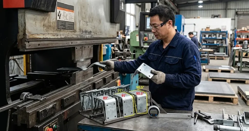
Record three things for a sample of parts: the part number in the run, the measured angle at a fixed station, and which blank bundle the sheet came from. Then match what you see to one of the patterns below.
Two of these get blamed on the wrong suspect most often. The step change gets called “the machine moved” when the step lands on a coil change, and the random scatter gets called “bad tooling” when the tooling is the one thing that has not varied.
Material Variation Between Sheets and Coils
In air bending, the sheet is the fixture: it rests on the die shoulders and the angle forms from how far the punch drives it. Anything that changes the sheet changes the angle, and the variables travel with the material — through the tolerance band of the grade, across the width of a sheet, along a coil, and between the mills that supply them. The controller can only program averages; each sheet brings its own reality.
Actual Sheet Thickness and Tolerance Variation
The tolerance zone you bought is wider than the tolerance your program assumes. As this analysis of angular variation on the press brake records, one common structural grade (A36) carries a tensile range from 55,000 psi to 79,800 psi against a 60,000 psi average, and one 16-gauge product specification allows 0.053 in to 0.067 in — and both are “within spec,” in that article’s worked example. The exact band depends on the standard, product form and grade you actually buy, so treat these figures as an illustration of how wide a single gauge’s zone can be, and check the specification that governs your own material.
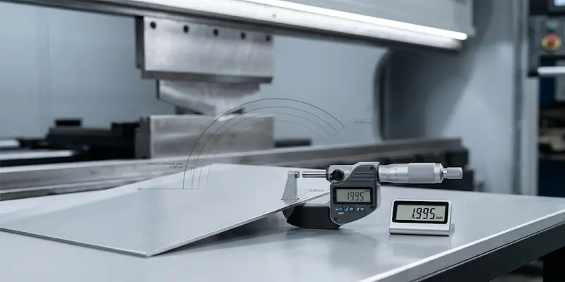
Thickness is not constant within one sheet either. Even within a single sheet, the thickness can vary across the width because of the rolling process, and one technical review of air bending puts the accuracy achievable with manual correction at about ±1°, naming within-sheet thickness variation and rolling-direction effects as the reasons. Even small thickness variations can produce measurable bend angle changes in air bending, particularly when using narrow V dies or working with tight angular tolerances. The actual sensitivity depends on material properties, tooling geometry and the bending setup — which is why the working habit is to measure the response on your own machine rather than quote a universal conversion.

Three habits catch thickness problems before they cost a batch:
- Mic the blanks, not the bundle label. Measure at the bend line, on both sides, on parts from the start, middle and end of the run.
- Log thickness by coil, not by purchase order. A coil change is the single most common step change in batch angle.
- Correct per coil, then lock the correction. When a new coil needs a different depth or a different springback allowance, record it against the coil tag so the next operator does not rediscover it.
Yield Strength and Springback Variation
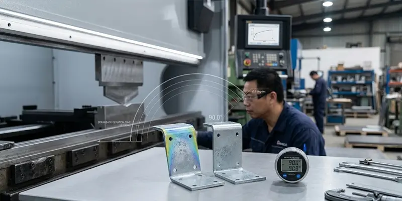
Two sheets of identical thickness can still leave the die at different angles, because the unloaded angle depends on how much the material springs back — and springback is a material property, not a machine setting. It increases with the yield point, with strain hardening and with die width, and the yield point is the largest single influence, per SSAB’s press bending guide.
Yield strength is exactly the property that varies inside a grade. For the A36 example above, yield can run from the 36,000 psi minimum to around 43,000 psi — a spread of roughly 13% — from heat to heat, as the same bending literature documents. Higher-yield heats spring back more at the same penetration, so the unloaded angle moves between coils, between mills, and even between the head and tail of a long coil.
What this does not mean is that springback always behaves badly. When material, tooling and machine are uniform, springback is consistent enough to compensate with a fixed allowance — that is why a well-set program holds angle for thousands of parts. The batch problem appears when one of those inputs moves and the allowance no longer matches. Because the offset is not guaranteed to be identical on every part, measure several parts at several stations before you conclude that the whole allowance is wrong; our guide to springback covers how to predict it and compensate for it properly.
If the material keeps moving and the tolerance is tight, many advanced CNC press brake controls support programmable springback compensation, and systems with in-process angle measurement close the loop per bend instead of per batch. That is the durable answer to a material you cannot control — more on it in the prevention section below.
One deliberate option for taming material variation is bottoming: pressing the sheet fully against the die so the die geometry, not the material, sets the result. Bottoming can reduce the sensitivity of the final bend angle to certain material variations because the workpiece is pressed more closely against the die geometry. However, it does not eliminate the effects of material properties or thickness variation. The required forming force is substantially higher than in air bending, so machine capacity, tooling load limits and the manufacturer’s operating recommendations must be verified before changing the forming method.
Grain Direction and Material Anisotropy
Rolling aligns the grain, and forming with the grain takes less forming pressure than forming across it, as the angular-variation analysis cited above notes. The pressure difference is not the whole story, though: formability, springback and cracking risk can all differ with direction, and by how much is a property of the specific material and temper — not a universal constant. The working rules are therefore consistency and verification rather than memorized numbers. Nest blanks with the same orientation run to run where the design allows, so a batch is not silently split into two forming behaviors, and confirm critical materials with a test bend in both orientations before committing a batch.
Differences Between Coils and Material Suppliers
A “batch” that was actually slit from two coils, or two lots from two mills, is two different materials wearing one job number. Sorting parts by blank bundle and measuring one from each bundle settles it in minutes. Purchasing practice matters here too: percentage-based corrections hold best when material comes from a single supply house, because different mills sit in different parts of the tolerance band, a point the air-forming literature makes explicitly. When a new coil or a new supplier arrives, bend a test coupon from it before running, and record any correction against the coil tag rather than leaving it for the next shift to inherit.
Setup and Tooling Variables That Change Mid-Run
Material gets blamed for everything, but several batch-level variables live on the machine side, and they have signatures the pattern table picks up.
- Tooling that has not seated. After a die change, the first strokes settle punches and dies into their seats. Parts bent before that settling finishes sit at a slightly different depth than the rest of the run. This is the classic “first parts off” signature, and it costs nothing to prevent: bend two or three setup coupons and re-measure before starting the count.
- A correction someone edited. A depth correction or springback value entered at part 60 produces a step change at part 60. If the program’s correction history is not logged, interview the shift; most step changes trace to an edit, not to physics.
- Different tooling segments. A die segment swapped from another set mid-run changes the effective V geometry where it sits. Unlike gradual wear, this shows up as a step or a second population, not a drift.
- Handling and positioning. Sheets that are not consistently against the backgauge fingers, or that are flipped so grain direction alternates between parts, produce scatter that looks like bad material. Watch one full cycle before judging it.
- What tooling wear is not. Gradual tooling wear is unlikely to explain random angle changes over a short production run — hardened tooling does not wear fast enough to move angles part to part. However, sudden tool damage, debris, incorrect seating or movement within the clamping system can produce immediate variations. The evidence test differs between the two: scatter that appeared right after a crash, a cleaning or a die swap is a tooling event worth inspecting; scatter with no such event points at material or handling first.
The pattern table separates these from material quickly. A step that coincides with a setup event is a setup variable. Scatter that survives identical setup on kept-aside material is material. Neither responds to the other’s fix.
Machine Warm-Up, Hydraulics and Thermal Drift
The machine itself is a variable in a batch, and it changes state at the start of every shift. Cold hydraulic oil is stiffer, so pump behavior, valve response and ram settling differ until the system reaches operating temperature. The frame and tooling also grow slightly with heat as cycling continues. None of this is large, but on a ±0.5° tolerance it does not have to be. The details differ by drive concept — a servo-electric brake has no oil viscosity to change, and hydraulic, hybrid and electric designs warm differently — so treat the mechanism below as typical of hydraulic machines and calibrate the routine to your own equipment.
The signature is specific and cheap to confirm: parts bent early in a cold shift sit slightly off the parts bent mid-shift, in a consistent direction, on every shift that starts cold. Keep the early cold-start parts aside and compare them with parts bent after the machine has been cycling — if the two groups differ by the same small offset on multiple shifts, you are looking at warm-up, not at material.
Two setup-level disciplines remove most of it:
- Follow the manufacturer’s warm-up procedure — then make it repeatable. The required warm-up cycles and stabilization time depend on the machine design, the operating environment and the production conditions, so base the startup routine on the manufacturer’s recommendations and on your own measurements, and hold the same routine on every shift.
- Re-check the first article once the machine is at its normal operating state. If a cold-start offset is real on your machine, either let the warm-up finish before first-article approval or re-approve the first article afterward.
One related trap belongs to the machine but wears a material costume: a crowning value left over from the previous job. It does not vary during the run, so it does not cause batch inconsistency — but it puts the whole batch at a small uniform offset that then gets “corrected” with material sorting. If every part is off by the same amount in the same direction, check the compensation settings first; our crowning systems page covers how the value should be derived from the job, not inherited from the last one.
Machine Positioning and Repeatability
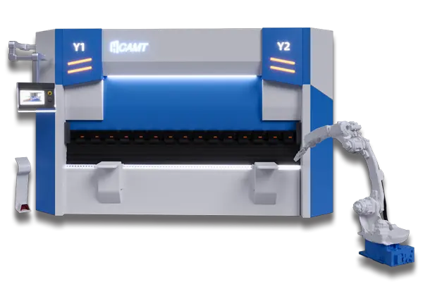
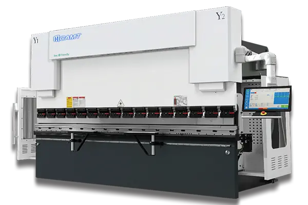
Between the material variables and the process habits sits the machine’s own positioning system. On a modern CNC press brake, the ram is positioned at each end by the Y1 and Y2 axes, and the control closes the loop on them through feedback from encoders or linear scales — so the ram depth the program asked for and the depth the machine actually reached are compared on every stroke. Repeatability on these axes is measured in hundredths of a millimeter, smaller than the material variations described above, which is why a healthy positioning system is rarely the explanation for batch scatter.
The exception is a positioning system that has quietly stopped being healthy. A drifting scale, a loose mounting or an unequal calibration between the two sides produces either a consistent offset or variation that no material explanation matches. The pattern table helps here: material scatter follows the blank bundles, while a left-right difference or a pure taper points at the positioning side. If adjacent coupons from one sheet disagree, the tooling checks clean, and no positioning or measurement error explains it, have Y1/Y2 and its feedback inspected and calibrated. Our CNC control systems page describes the closed-loop positioning and feedback hardware behind that check, and scheduled calibration is cheaper than discovering the drift during a defect claim.
The Isolation Protocol: One Variable at a Time
When the pattern does not hand you the answer, the discipline that finds it is the same one a good shop uses everywhere else: never change two things at once. The protocol below is short, and every step produces a conclusion rather than a guess.
Step 3 is the pivot of the whole protocol, and it is the step shops get wrong most often. Re-bending a part that has already been bent proves nothing: the first bend has already changed the material’s local plastic state and geometry, so the second stroke does not start from the same conditions. The comparison has to be built from two coupons cut adjacent to each other from the same kept-aside sheet or the same coil, identical in size and orientation, bent back to back under unchanged settings. Those coupons share the sheet’s thickness profile, strength and grain direction, so a difference between them can only come from the machine, the setup or the measurement.
That is a conclusion, but a limited one. A coupon difference clears the material and indicts the machine side — it does not by itself name the culprit, because positioning, handling and reading error are still suspects until steps 1 and 6 have closed them out. Two adjacent coupons that agree, followed by parts from different bundles that disagree, is the cleanest material verdict the shop floor can produce, and everything after it is just deciding which variable to fix.
Worked Example: 120 Brackets Across Three Shifts
A shop runs 120 brackets from 2 mm mild steel, target inside angle 90° ± 0.5°, same program, same tooling, three shifts. The complaint: “the batch is inconsistent.”
The pattern table does the first cut. Parts 1–40 measure 90.1°–90.4°. Parts 41 onward open progressively to 91.3° by part 90, then hold. On shift two, the first few parts measure about half a degree open again before the run settles back. Scatter at any point in the run is tight — parts bent minutes apart agree to a tenth of a degree.
That is two patterns, not one: a step-with-drift starting near part 41, and a cold-start offset on shift two. The isolation protocol sorts them. Step 3 — two coupons cut side by side from the same kept-aside sheet, bent back to back — agree within 0.1°, so the machine and handling are repeatably fine. Step 4 — parts from the first bundle versus parts from the second — reproduces the whole 1°+ difference. Micrometer work on both bundles shows the second coil running a few hundredths of a millimeter thicker at the bend line, and the material tag on bundle two shows a different coil than bundle one.
The causes, in order of impact: a coil change at part 41 moved the angle outside tolerance under a program tuned to the first coil, and the shift-two morning offset is cold-machine warm-up. The fixes follow directly — a test coupon and, where needed, a recorded depth correction per coil at every changeover, and a repeatable warm-up routine before the first article on each cold start. No tooling was replaced, no machine was “fixed,” and the next batch of 120 holds tolerance throughout.
The example is worth keeping because of what the evidence ruled out. Nothing in the run drifted within a coil, so the machine’s repeatability was never in question — chasing it with a service call would have found nothing.
Keeping the Next Batch Consistent
None of the fixes above are exotic. They are process habits, and the shops that hold angle batch after batch run all of them:
- First article, plus scheduled in-run checks. Approve the first part after warm-up, then re-check every 20–25 parts or at every material and setup event, whichever comes first. A step change caught at part 45 costs one part; caught at part 120, it costs a batch.
- Material identity travels with the batch. Coil tag, mill certificate and measured thickness, logged against the job. Every diagnosis in this article gets faster when the parts can be traced to their material.
- Lock the program between material events. Corrections get recorded against the coil tag they were tuned for, not left for the next shift to inherit or “fix” by eye.
- Standardize warm-up and setup coupons on every shift start and every tooling change, so the first production part is bent with a settled machine and a repeatable startup routine.
- Nest with consistent grain orientation where the design allows, so the batch is not silently split into two forming behaviors.
- Close the loop where the material varies anyway. When tolerance is tight and incoming material moves, in-process bending angle measurement reads the angle during the stroke and corrects the depth per bend, which takes sheet-to-sheet variation out of the operator’s hands instead of asking the schedule to wait for perfect steel.
The pattern behind all six habits is the same: make the variables visible before they become scrap. A batch with angle problems and no material tags is a mystery; the same batch with tags, timestamps and scheduled checks is usually a fifteen-minute diagnosis.
If the angles are wrong in a way this article does not describe — along the part instead of between parts, or alongside other defects — the full defect list and its causes live in our press brake troubleshooting guide, and our engineers will help read a stubborn run if you send the part data through technical support.
FAQ About Why Parts From One Batch Have Different Bend Angles