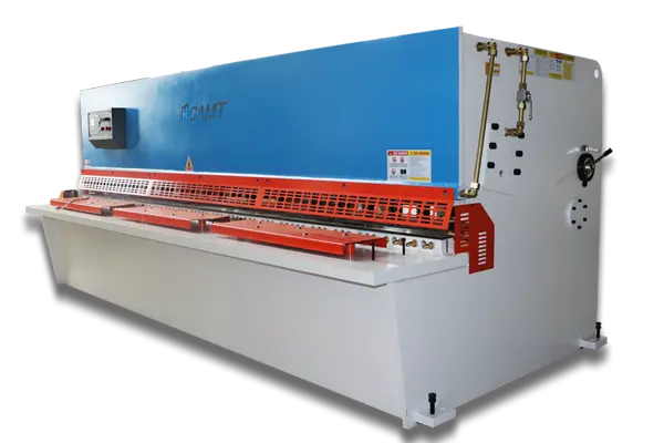
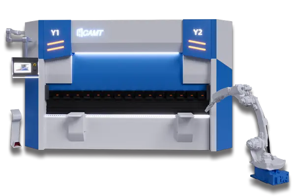
Choosing the right press brake is not simply about selecting a machine with enough tonnage or the longest working table. The right equipment must match your material specifications, bending requirements, production volume, accuracy targets, and future manufacturing plans. A machine that is undersized may struggle with thicker materials and long bends, while an unnecessarily advanced model can increase your investment without delivering meaningful productivity improvements.
The order that works is from the parts backward:
- The longest bend you run every week sets the working length — and the distance between the uprights, which is not the same number.
- The thickest material you form routinely (not once a year) sets the tonnage.
- The deepest flange, box or return sets the throat depth and the open height.
- The variety and tolerance of your work sets the controller and the number of backgauge axes.
- The tooling you already own sets the clamping interface — or the cost of replacing it.
1. Define Your Production Requirements Before Choosing a Press Brake
Before comparing manufacturers or requesting quotations, start with the parts you actually produce. Many purchasing mistakes happen because buyers select equipment based on a familiar tonnage rating or an attractive price rather than their real production requirements. A press brake should be selected according to the most demanding bending applications you regularly expect to handle — not simply your average job, and not the single heaviest job you ever quoted.
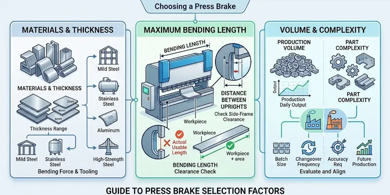
Identify Your Materials and Thickness Range
Different materials require different bending forces and tooling configurations, even at identical thicknesses:
- Mild steel — structural components, machinery frames, electrical enclosures, general fabrication.
- Stainless steel — higher strength and work-hardening; generally requires more bending force.
- Aluminum — bending behavior varies considerably by alloy and temper.
- High-strength steel — demands careful attention to springback, tooling loads, and machine capacity.
Record the minimum, typical, and maximum thicknesses you process, and the actual grades and tensile-strength ranges wherever possible. Then separate the work you run every week from the work that shows up occasionally: a workshop that primarily bends 2 mm mild steel but occasionally processes 6 mm stainless steel should not size its machine on the 2 mm workload alone, but neither should it buy for a 6 mm job it has never actually won. The occasional heavy application may decide the capacity — include the parts you currently turn away, because the specification stage is the cheapest moment to expand what the shop can take on.
Determine Your Maximum Bending Length
The longest bend you need is the second major selection factor. A press brake’s nominal working length does not automatically mean every workpiece of that length can be processed without interference: side-frame clearance, throat depth, workpiece geometry, and tooling arrangement all affect the usable bending area. Check the actual distance between the uprights rather than relying exclusively on the nominal bending length — this catches long cabinet panels, structural components, and architectural sheets.
Evaluate Production Volume and Part Complexity
Two factories producing the same components may need very different machines. Evaluate:
| Production factor | What to consider |
|---|---|
| Daily output | Parts and bending operations per shift |
| Product variety | Number of different part designs and dimensions |
| Batch size | Large repetitive batches or frequent small orders |
| Changeover frequency | How often operators change punches and dies |
| Accuracy requirements | Angle, flange dimension, and repeatability tolerances |
| Future production | Expected changes in material, part size, and order volume |
2. Choose the Right Type of Press Brake
There is no “absolute best” press brake — only the best press brake for your operation, your parts, and your operators. Press brakes are available in several configurations, each designed for different production priorities; choosing the wrong type leads to unnecessary investment, insufficient flexibility, or higher operating costs.
NC Press Brake: A Practical Choice for Standard Bending
NC machines typically use a simpler control and torsion-bar synchronization — on our range, this is the economical 2-3 axis torsion-bar series. They suit workshops producing standard components with straightforward bending sequences: lower initial investment, straightforward operation, and practical for repetitive work. The trade-offs are less flexibility for complex multi-step bending, more manual adjustment, and longer setup on varied products.
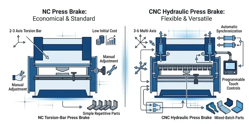
CNC Hydraulic Press Brake: Flexible and Versatile Production
CNC hydraulic machines combine hydraulic power with electronic control and precision synchronization, and they remain the workhorse class of modern fabrication. Depending on configuration they provide multi-axis backgauge positioning, automatic ram synchronization, programmable sequences, CNC crowning compensation, and optional angle measurement — the breadth that mixed-batch shops, enclosure manufacturers, and stainless panel work need. Our Smart 3-4 axis and Genius 4-6 axis series sit in this class.
Hybrid Servo Press Brake: Precision with Improved Energy Efficiency
Hybrid servo machines pair hydraulic force with a servo-controlled pump: instead of running continuously at fixed output, the drive adjusts to the machine’s actual demand, cutting idle consumption, oil circulation, and heat generation. Our Apex 6-8 axis hybrid series works this way, with the hybrid servo ECO function backing the pump off between strokes. One honest caveat: energy savings depend on configuration, cycle profile, and idle time — request actual power-consumption figures rather than relying exclusively on general marketing percentages.
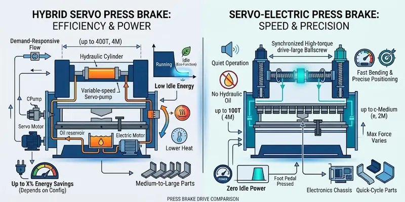
Servo-Electric Press Brake: High-Speed Precision Bending
Servo-electric machines drive the ram with servo motors rather than a hydraulic power system: fast response and positioning, high repeatability, quiet operation, and no hydraulic oil in the drive. Because an electric machine draws little power until the pedal is pressed — where a conventional hydraulic pump runs continuously — the advantage concentrates on small, quick-cycle, high-mix work; on parts above roughly a metre in length, material handling dominates the cycle and the drive choice matters less (Canadian Metalworking). Our EPB servo-electric series targets exactly that profile. Maximum tonnage, working length, and heavy-plate capability must be evaluated carefully — servo-electric is not automatically the best choice for thick plate or very high bending forces.
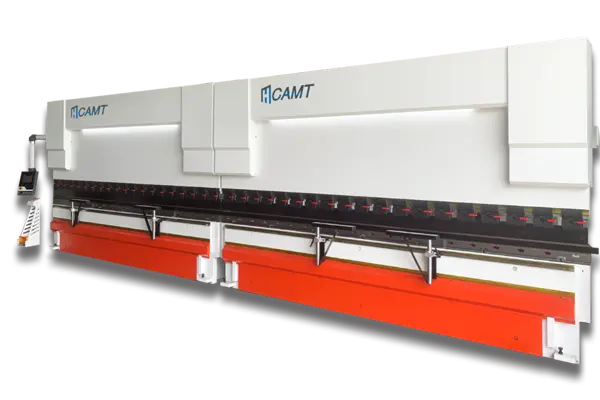
Tandem Press Brake: For Extra-Long Workpieces
A tandem system synchronizes two or more machines to process workpieces longer than any single bed: long architectural panels, railway components, structural sections, oversized enclosures. The investment is justified when long workpieces are a regular part of production rather than occasional exceptions, and it requires careful synchronization, layout planning, and control integration.
Which Press Brake Type Should You Choose?
| Machine type | Best suited for | Main consideration |
|---|---|---|
| NC (torsion-bar) | Standard, repetitive bending | Lower investment, fewer advanced functions |
| CNC hydraulic | General and complex fabrication | Flexible control, broad application range |
| Hybrid servo | Precision production with energy priorities | Higher initial investment and configuration |
| Servo-electric | Thin/medium sheet, high-speed precision | Tonnage and heavy-plate limitations |
| Tandem | Extra-long workpieces | Synchronization and installation requirements |
Explore our full press brake range to compare the available configurations, or jump to the series-matching table in Section 11.
3. Calculate the Capacity: Tonnage and Machine Dimensions
What Affects Required Tonnage?
Five factors determine the bending force you need:
- Material thickness — force rises approximately with the square of thickness under comparable air-bending conditions.
- Material strength — higher-strength materials require more force.
- Bending length — longer bends need greater total force.
- V-die opening — a narrower opening increases required force.
- Bending method — air bending, bottoming, and coining sit at different force levels.
The Tonnage Calculation Formula
For preliminary planning, a commonly used air-bending formula for mild steel is:
Tons per foot = 575 × t² ÷ V
where t is material thickness in inches, V the lower die opening in inches, and the 575 factor assumes air bending of mild steel on a nominal tensile-strength basis around 60,000 psi. For a complete bend, multiply by the bend length in feet.
Worked example: air-bend a 1/4-inch mild steel plate over a 10-foot length with a 2-inch V-die.
- Tons per foot: 575 × 0.25² ÷ 2 = 17.97
- Total: 17.97 × 10 = ≈ 180 US tons
For metric planning, the equivalent working form is P (kN) ≈ 1.33 × σb × S² × L ÷ V, where σb is tensile strength in MPa, S thickness in mm, L bend length in mm, and V the die opening in mm; the 1.33 coefficient is a common approximation and variants exist between references, so state which one your calculation uses.
Either way, the result is an estimate, not an approval. Confirm the final load against the machine manufacturer’s tonnage chart and the tooling maker’s specifications, using the material’s certified strength and the real bend geometry.
How Much Extra Tonnage Should You Allow?
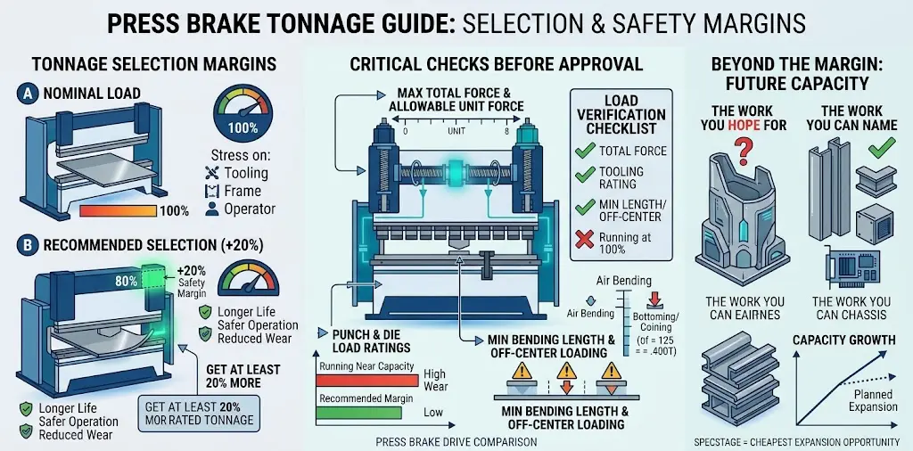
Do not select a machine that operates continuously at its rated maximum. Steve Benson’s standing advice for new press brake purchases is to get at least 20 percent more rated tonnage than you think you need, because running at or near rated capacity is hard on the operator, the tooling, and the machine’s working life (The FABRICATOR) — beyond that margin, size for the work you can name, not the work you hope for. Also remember that bottoming and coining push force requirements substantially above free air bending for the same part, and the increase must be calculated per job rather than assumed.
Verify, before approving:
- Maximum total bending force, and allowable force per unit length.
- Minimum bending length and permitted off-center loading — a machine can have enough total tonnage yet be unsuitable for concentrated or off-center bends.
- Punch and die load ratings: the machine may deliver the force, but the die standing under it has its own per-metre ceiling — our tooling load guide covers that check separately, and a purchase order should clear both limits.
Working Length, Uprights, Throat and Open Height
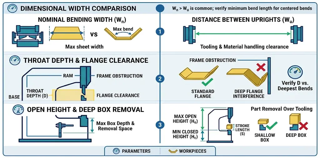
Tonnage alone does not make a machine fit your parts. Read the spec sheet with these distinctions:
Bending width is not the distance between uprights. On our own servo CNC tables, for example, the 110 T / 3200 mm model lists a maximum bending width of 3200 mm but a distance between uprights of 2700 mm. The bed can carry a 3.2-metre sheet, but the tool length that physically fits between the uprights is shorter — and tool length caps the bend you can run in one hit. Read both numbers against your longest single bend, not just the sheet size.
Throat depth decides where the bend can sit — the open distance from the machine front back to the uprights, typically 300-500 mm across our range. Deep electrical cabinets, large enclosures, U-shaped components, and deep-flanged parts that position bends well back from the sheet edge all make throat depth a must-have, best evaluated with actual part drawings.
Stroke and open height decide whether the part comes out. Open height is the daylight between upper and lower tooling at full raise; together with ram stroke and die-setting height it governs tooling stacks and part removal. A deep box with inward return flanges is the classic case that gets stuck on a machine sized by tonnage alone — our guide to bending deep boxes and cabinets without tooling interference walks through the clearance arithmetic before you sign.
| Specification | Why it matters |
|---|---|
| Bending length | Maximum nominal bend length |
| Distance between uprights | Side clearance — and the real tool-length limit |
| Throat depth | Clearance for deep or wide parts |
| Ram stroke | Available vertical movement |
| Open height | Space for workpieces and tooling |
| Die-setting height | Compatibility with the tooling arrangement |
| Working height | Operator ergonomics and material handling |
Read the speed columns for what they are, too: approach, working, and returning speeds are listed separately because the working speed is where angle quality lives, and a spec quoting one impressive number is usually quoting the one that matters least for accuracy.
4. Choose the Right CNC Controller and Backgauge Configuration
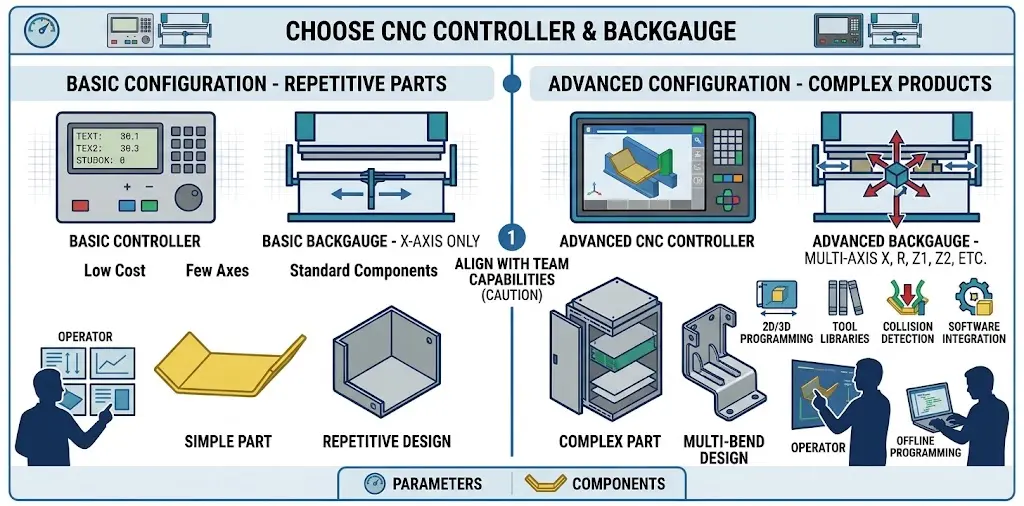
The controller and backgauge directly influence flexibility, programming efficiency, and operator productivity. A basic machine suffices for simple repetitive components; complex products need multiple positioning axes and sequence control. Depending on configuration, advanced functions include automatic bending sequence calculation, 2D/3D part programming, tool libraries, collision detection, offline programming, automatic crowning calculations, and integration with production software — see our CNC control system options for the configurations available.
One caution earned in real shops: before paying for more than basic axis control, look at the operators who will run it. Controller functions earn their cost only if your team actually uses them, and an operator team that quietly prefers the old machine can undermine the return on a new one (The FABRICATOR). The same logic applies to offline programming — it pays when program preparation happens while the machine bends, and sits idle when the part mix doesn’t support it.
How Many Backgauge Axes Do You Need?
| Backgauge configuration | Typical axes | Suitable applications |
|---|---|---|
| Basic | X | Simple flange positioning |
| 2-axis | X, R | Standard bending with adjustable gauge height |
| 4-axis | X, R, Z1, Z2 | Complex parts, independent left/right positioning |
| 6-axis | X1, X2, R1, R2, Z1, Z2 | Advanced asymmetric and multi-stage bending |
A higher axis count does not automatically mean higher productivity: a 2-axis configuration may be enough for simple brackets, while high-mix production with different flange positions justifies more axes. On our Genius series, for instance, the Z1/Z2 fingers reposition from the program automatically between batches — a very different production proposition from nudging stops by hand. The best configuration is the one that eliminates your actual production bottlenecks; our backgauge system selection guide compares them in detail.
5. Evaluate Bending Accuracy and Crowning Systems
Bending accuracy is not determined by the CNC controller alone. Under bending load the frame, ram, and worktable deform — often more in the center than at the ends — so the angle can vary along the workpiece and flange dimensions drift, most noticeably on long bends and high loads.
Crowning compensates for that deformation by introducing a controlled adjustment to the lower beam or table, keeping contact conditions consistent along the bending length. Configurations range from mechanical and motorized mechanical to CNC-controlled and hydraulic crowning; for long sheets or full-length angle consistency, it belongs in the purchasing evaluation, not the retrofit wish list — see our press brake crowning systems. One limit to keep in mind: crowning cannot compensate for every source of variation. Material thickness variation, tensile-strength differences, tooling wear, machine alignment, and programming errors must also be controlled.
For tight-tolerance work, automatic angle measurement reduces trial bends and manual inspection: sensors measure the actual angle and feed correction back into the process — valuable when material properties vary between batches, tolerances are tight, or sequences are long and complex. See angle measurement systems, and before purchasing, ask the manufacturer to demonstrate measurement and correction using your actual material and workpiece geometry.
6. Check Tooling Compatibility and Clamping Systems
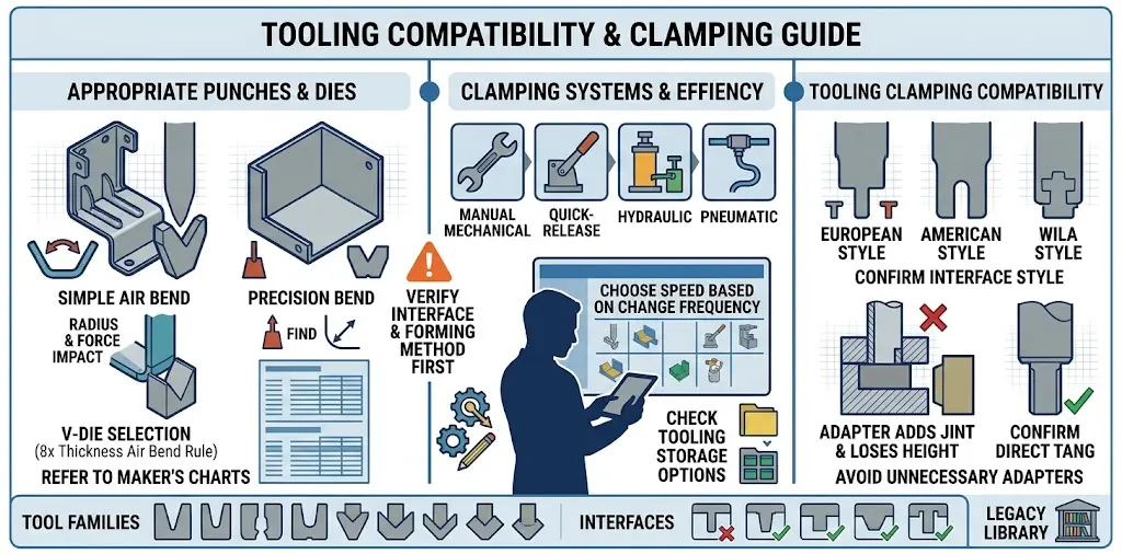
A press brake is only as effective as the tooling that touches the part — and the tooling decision should influence the machine decision, not trail it. As Steve Benson puts it, when selecting a new press brake, consider first and foremost the tooling style and forming method; starting anywhere else is how costly mistakes happen (The FABRICATOR). His advice carries a warning from a real buyer’s letter too: a shop that bought a new brake, then discovered its new tooling didn’t match its stock tooling and needed adapters to keep legacy tools running — and adapters cost open height and add a joint in the load path.
Choose the Appropriate Punches and Dies
The tooling configuration affects inside bend radius, minimum flange length, required force, surface finish, and the maximum achievable part geometry. For air bending of mild steel, a common starting point is a V-die opening around eight times the material thickness — the correct opening depends on material, inside radius, flange dimensions, and bending method, and a smaller opening increases force while a larger one produces a larger radius. Our V-die selection guide works through the choice, and the tooling maker’s bending charts and load limits always take precedence over rules of thumb.
Consider Tooling Clamping Compatibility
Clamping determines how quickly and safely operators change tools: manual mechanical, quick-release, hydraulic, pneumatic, or WILA-style quick-change systems. Frequent product changes justify faster clamping — see our tooling clamping solutions and tooling and storage options. If you already own European-style, American-style, or WILA tooling, confirm the interface before ordering: the tang style is a specification you can order against, and keeping your library working is usually cheaper than replacing it. Our tooling guide and tooling compatibility guide cover the families, the seat and stack checks, and the adapter trade-offs in detail.
7. Consider Automation and Material Handling Requirements
Automation should be evaluated against production volume, labor availability, part complexity, and the consistency you need. Manual operation stays flexible and cheap to start, but as volume grows, manual positioning and handling become the bottleneck.
Automated bending can reduce repetitive handling, improve consistency, raise output for suitable parts, and support longer runs. Options include robotic bending cells, automatic loading and unloading, sheet followers and front supports — our bending follower supports carry the sheet as it rotates so the operator isn’t fighting the part’s weight — integrated production lines, and centralized offline job preparation. Not every workshop needs a full cell: for frequent small-batch orders, a well-configured CNC press brake with the right backgauge often delivers better value than a robotic system.
8. Evaluate Machine Safety and Operator Protection
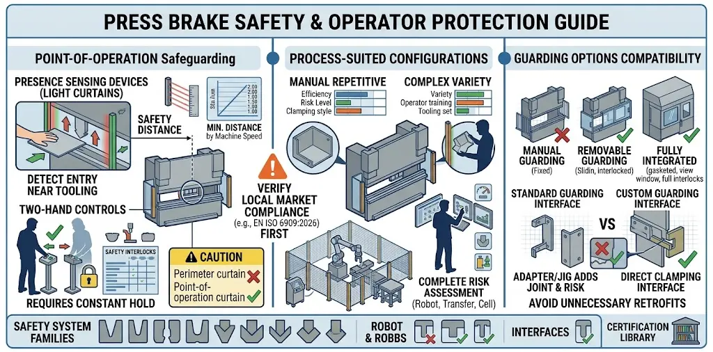
Safety is never an optional purchasing feature. Press brakes generate significant force, and the guarding conversation belongs in the buying conversation — retrofit budgets are always tighter than purchase budgets.
OSHA’s machine guarding eTool lists the recognized point-of-operation safeguarding options for press brakes: presence sensing devices (light curtains), two-hand controls, pullback, and restraint devices (OSHA Machine Guarding eTool). One detail from that guidance matters at specification time: perimeter or work-envelope curtains sold for area guarding must not be used for point-of-operation protection — specify a point-of-operation-rated device with the safety distance calculated for your machine.
Confirm that the proposed machine complies with the machinery safety regulations of your destination market. In Europe, press brake safety requirements are set by EN ISO 6909:2026, which replaced the earlier EN 12622 standard. The safety configuration should suit the machine’s speed, tooling arrangement, and process — and if you plan robotic automation, the risk assessment must cover the robot, transfer equipment, guarding, and the complete cell. Our safety arrangements page lists the guarding, control, and training options available at the factory.
9. Compare Total Cost of Ownership and the Manufacturer Behind the Machine
A lower purchase price does not necessarily mean a lower long-term investment, and a competitive quotation means little if the supplier cannot support the machine after installation. Evaluate both together.
Make the Quotations Comparable
Initial cost may include the machine, controller and axes, punches and dies, clamping, crowning, safety equipment, transport, installation, and foundation or electrical preparation. A lower quote may simply exclude tooling, backgauge options, or commissioning — insist that all quotations define the same scope before comparing numbers.
Add Up the Operating Years
Long-term costs include electricity, hydraulic oil and filters, seals and consumables, tooling maintenance, preventive service, spare parts, technical support, training, and downtime. For hydraulic machines, check the availability and cost of critical hydraulic components; for servo-electric or hybrid models, evaluate drive, controller, and service requirements.
Judge the Return on Evidence, Not Promises
The most useful comparison is how the machine changes production cost and output: less scrap and rework, fewer trial bends, shorter setups, lower energy draw, more parts per shift. But projected savings should be supported by actual production data or a supplier demonstration on your material — not assumed from performance claims.
Evaluate the Manufacturer
Ask about frame design and structural analysis, welding and stress-relief processes, machining accuracy, component brands, assembly procedures, and final inspection; request a factory or independent pre-shipment inspection where possible. Before signing, clarify warranty coverage, spare-parts availability, remote troubleshooting, response times, on-site service, and software support. CAMT supports customers across the equipment lifecycle with technical support, maintenance and upgrades, and operator training.
10. Purchasing Checklist: What to Confirm Before Ordering
Use this checklist to make sure no critical specification has been overlooked, then verify it on real parts.
| Evaluation item | Questions to confirm |
|---|---|
| Material | What materials and grades will the machine process? |
| Thickness | Minimum, typical, and maximum thicknesses covered? |
| Tonnage | Has the bending force been calculated and margin applied? |
| Working length | Can it handle the longest workpiece — and longest tool? |
| Machine clearance | Are throat depth and distance between uprights sufficient? |
| Stroke and open height | Room for the required tooling and part removal? |
| CNC controller | Does it support the required programming functions? |
| Backgauge | Are the axes sufficient for your part geometries? |
| Crowning | Required for long or high-load bending? |
| Tooling | Are punches, dies, and clamping compatible — with existing tools too? |
| Safety | Does it meet your market's safety requirements? |
| Automation | Are future automation interfaces available? |
| Electrical | Does it match your factory's power supply? |
| Warranty & training | What is covered, and is installation and operator training included? |
| Spare parts & delivery | Are critical components available; are schedules defined? |
Request a Trial Bending Test Before Final Approval
Provide your actual part drawings and material, and ask the supplier to demonstrate:
- Bending your specified material and thickness.
- Achieving the required angles and holding flange dimensions.
- Consistent results across the full bending length.
- Complex sequences without tool or workpiece interference.
- All relevant safety systems in operation.
Measure the finished parts rather than relying on advertised positioning accuracy — a successful bending test is more meaningful purchasing evidence than a general machine demonstration.
11. Matching the Machine to Your Shop: The CAMT Range
The table below compresses this guide into the question buyers ask last: which machine, for whom?
| Your shop profile | The CAMT series that fits | Why |
|---|---|---|
| Budget-driven, repeat flanges and simple work | Economical 2-3 axis | Torsion-bar sync keeps cost down where program complexity is low |
| General fabrication, mixed everyday batches | Smart 3-4 axis | Stored programs and programmable gauges for job-shop part mix |
| High-mix, tight angles, complex multi-bend parts | Genius 4-6 axis | Auto Z1/Z2 repositioning, 2D + 3D programming, ±0.5° rating |
| Thin precision sheet, clean and energy-sensitive production | EPB servo-electric | No hydraulic oil, fine servo positioning, power only on the stroke |
| Mixed thin-to-medium work with automation plans | Apex hybrid 6-8 axis | Hybrid drive efficiency with the axis count for complex parts |
| Long workpieces — poles, panels, structural | Tandem solution | Two synchronized machines extend the bed and the flexibility |
| Thick plate, high-strength materials, heavy tonnage | Heavy-duty series | Frame rigidity and force for demanding plate work |
| Repetitive panel parts, lights-out ambitions | Robotic bending cell | Integrated automation for consistent repeat production |
If your profile straddles two rows — most shops’ do — the deciding votes come from Section 1: the weekly work picks the row, and the aspirational work breaks the tie. Rather than selecting a machine on tonnage alone, share your material specifications, part drawings, production volume, and accuracy requirements before finalizing a configuration.
Looking for a press brake that matches your actual production requirements? Explore CAMT press brake solutions or contact our team to discuss your application and request a customized quotation.
Start anywhere in this series
Each screen of the decision has a guide of its own.
FAQ
What is the most important factor when choosing a press brake?
Whether the machine can reliably process your actual workpieces. Material type, maximum thickness, bending length, required tonnage, and part geometry should be evaluated together; CNC configuration, tooling, accuracy, and production volume then narrow the choice. Start from the parts, not the specification sheet.
How do I calculate the tonnage required for a press brake?
For preliminary air-bending estimates on mild steel: Tons per foot = 575 × thickness² ÷ V-die opening (inches), multiplied by bend length in feet. In metric, P (kN) ≈ 1.33 × σb × S² × L ÷ V. Apply a capacity margin — at least 20 percent over your calculated maximum is a common engineering baseline — then verify against the manufacturer’s tonnage chart and the tooling’s allowable load per metre.
Should I choose an NC or CNC press brake — and how many axes?
NC suits standard, repetitive bending with simple geometries and a tight budget. CNC earns its cost when part variety, complex sequences, or angle tolerances demand programmable axes and compensation. For axes: X alone handles simple flanges, X+R covers standard work, 4-axis adds independent left/right positioning, and 6-axis serves complex asymmetric multi-stage bending. Choose the configuration that eliminates your actual bottlenecks — extra axes nobody programs buy nothing.
Is a servo-electric press brake better than a hydraulic one?
Not universally — it matches your part mix. Servo-electric wins on thin, quick-cycle, high-mix precision work: fast response, fine positioning, no hydraulic oil, near-zero idle power. Hydraulics remain the natural choice for thick plate, long beds, and heavy tonnage, and hybrid servo designs split the difference. The electric advantage also shrinks as parts grow — above roughly a metre, material handling dominates the cycle regardless of drive type.
Do I need a crowning system on my press brake?
Crowning is particularly valuable when bending long workpieces or working under high loads, where frame deflection makes the angle vary between the center and the ends. Whether it is necessary depends on working length, tonnage, machine rigidity, and required accuracy — and remember crowning cannot compensate for material variation, tooling wear, or programming errors, which must be controlled separately.
What information should I send when requesting a press brake quote?
The part data, not a machine model: material grades and weekly thickness range, the longest single bend, your deepest flange and box, two or three representative drawings, angle tolerances, production volumes, the tooling you already own, plus your power supply, floor space, and delivery constraints. Ask for the tonnage calculation in writing and a trial bend on your material — that is how a supplier proves the machine fits the work instead of the budget line.