Tonnage and bending length get all the attention in a press brake purchase, and together they still do not answer whether your part can be made. Three dimensions do: bending length, throat depth and opening height. A machine can have enough force and a long enough bed and still fail on a deep enclosure, a wide rigid panel or a tall tooling stack — because the part cannot enter the machine, cannot sit where the bend line needs to be, or cannot come back out.
Size them from your drawings in this order:
- Bending length — your longest bend line, then the distance between uprights for anything that must pass through the frame.
- Throat depth — your deepest return flange or deepest bend-line position, plus tooling clearance.
- Opening height and stroke — your tallest tooling stack plus the room the formed part needs to be inserted, rotated and removed.
1. What the Three Dimensions Control
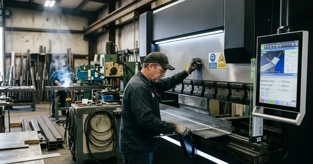
A press brake is not an empty space. Side frames, ram, bed, clamps, tooling and workpiece all compete for the same room, and each dimension measures that room from a different direction.
| Parameter | Direction | Question it answers | Failure when too small |
|---|---|---|---|
| Bending length (working length) | Along the bed | Can the bend line fit across the tooling? | Long parts bent in sections, accuracy loss |
| Distance between uprights | Along the bed, clear opening | Can the part pass through or rotate inside the frame? | Rigid wide panel cannot enter |
| Throat depth | Horizontal, into the frame | Can the bend line sit far enough from the sheet edge? | Return flange hits the side frame mid-bend |
| Opening height and stroke | Vertical | After tooling is installed, does the formed part fit and come out? | Box wedged in the machine, part cannot rotate |
Two definitions worth separating early, because they are routinely mixed up. Opening height (daylight) is the maximum vertical opening between ram and bed with the ram fully up, normally quoted before tooling. Ram stroke is how far the ram travels down from that position. Neither is the same as shut (die-setting) height, the closed-position figure. Manufacturers also draw the measurement reference lines differently — some quote daylight between tool holders, some from ram to table — so when two quotations look identical, ask each supplier what their opening-height figure references. That is why published figures have to be read as a set rather than as one capacity number: The Fabricator’s press brake buying guide treats tonnage, bending length and open height as three separate purchasing decisions, each with its own cost, instead of one headline specification.
2. Bending Length: Size to the Bend, Then Check Between the Uprights
Start with the longest bend line in your product range, not with the longest machine in your budget. A rough planning frame looks like this — preliminary ranges, not selection rules:
| Production requirement | Length class to evaluate |
|---|---|
| Small brackets, compact components | 1,250–1,600 mm |
| Medium sheet metal panels | 2,000–2,500 mm |
| Electrical cabinets, equipment housings | 3,000–3,200 mm |
| Long structural components | 4,000–5,000 mm |
| Oversized panels and profiles | 6,000 mm or tandem |
Then check the number that actually bites: distance between uprights. It is always shorter than the bending length, and the gap grows with machine size. Published figures from our Smart-series table:
| Model class | Max. bending width | Distance between uprights | Gap |
|---|---|---|---|
| 40T/1600 | 1,600 mm | 1,200 mm | 400 mm |
| 70T/2500 | 2,500 mm | 2,000 mm | 500 mm |
| 110T/3200 | 3,200 mm | 2,700 mm | 500 mm |
| 220T/4100 | 4,100 mm | 3,300 mm | 800 mm |
| 220T/5000 | 5,000 mm | 4,100 mm | 900 mm |
| 220T/6000 | 6,000 mm | 5,000 mm | 1,000 mm |
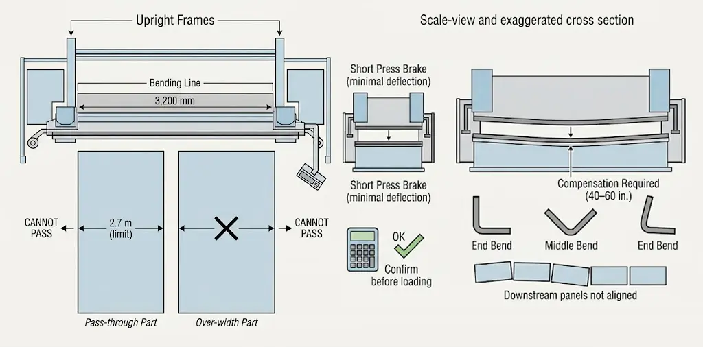
(Exact gaps vary slightly by tonnage class.) So a 3,200 mm machine bends a 3-metre bend line, but a rigid part wider than 2.7 m cannot pass through the frames or rotate inside them. If your parts must pass through the machine, the uprights figure is the real limit. And length is not free: every extra metre means more bed and ram to fill with tooling, more floor space, harder material handling, and a longer structural span that deflects more under load. As Cincinnati Inc.’s product manager put it in a Canadian Metalworking survey of crowning practice, “all press brakes’ bed and ram deflect under load,” and building a machine that does not is “cost-prohibitive” (canadianmetalworking.com). That deflection shows up as an angle that differs between the middle and the ends of a long bend, and downstream as panels that no longer align with their mating parts (sheetmetalindustries.com). Compensation belongs in the purchase conversation for long beds — builders and users interviewed in the same survey put the useful threshold at roughly 40–60 in. of bend length.
Longer also does not mean stronger. Required force grows with length at constant thickness, tensile strength and die opening (F ∝ L × t² × Rm / V); run your case through the press brake tonnage calculator rather than scaling from a neighbour’s machine, and confirm any restriction on off-center or concentrated loading before you commit.
3. Throat Depth: Where the Bend Line Sits

Throat depth is the horizontal distance from the tooling centerline back to the inner face of the side frame. The sizing test is arithmetic, not intuition: deepest return flange, or deepest distance from sheet edge to bend line, plus clearance for tooling shoulders, must be smaller than the throat. If it is not, no amount of tonnage helps — the options are a deeper-throat configuration, a different bend sequence, or a part redesign.
The dimension that matters is not the flat blank width. It is the geometry at each stage of the sequence: a flat sheet slides in easily, but after the first bend the formed flange occupies space it did not occupy before, and on the third and fourth sides of a box the walls sweep toward the frame. Deep cabinets, enclosures, channels and long return flanges are where throat depth becomes the deciding specification rather than a footnote.
Across our published Smart-series range, throat depth runs from 300 mm on the 40T/1600 to 400 mm through the 110–220T classes, 450 mm on the 250T class and 500 mm on long-bed 300T models; tandem configurations extend to 600 mm. Use those as checkpoints against your drawing. And do not over-buy: a deeper throat removes material from the side frame, so it has to be engineered and paid for, and a machine that never bends deep returns gains nothing from it.
Deep boxes add a second, tooling-side interference problem — how the formed walls clear the punch, clamps and die holder through the sequence. That arithmetic is covered in our guide to bending deep boxes and cabinets without tooling interference.
4. Opening Height and Stroke: Whether the Part Comes Out

The published opening height is a bare-machine figure. Once clamps, punch, die, holders and risers are installed, the usable space is smaller — sometimes much smaller. The check is:
Usable clearance = published opening height − tooling stack − room needed to insert, rotate and remove the part.
For four-sided parts the requirement climbs quickly, because the formed walls sweep upward toward the ram on the last bends. Practical starting points from a bending specialist writing in The FABRICATOR: punch height (or punch plus extender) at roughly 1.7 × box depth, at least 100–150 mm of working space between punch and die for boxes and four-sided parts, stroke length of at least half the open-height specification for 22–10 ga. work, and — when buying — “as much open height as possible,” because the work envelope “typically can’t be changed” after the frame is built (thefabricator.com).
Two caveats. The ×1.7 rule is written for standard clamping — heavy-duty clamping systems are wider front to back and widen the interference zone, so the calculation must be redone with the clamp you are actually buying. And a gooseneck punch does not automatically solve clearance: its height, profile and rated load all have to be checked against the machine and the part. If you are comparing clamping options, our tooling clamping system page covers the trade-offs.
For scale, our Smart-series table runs from 450 mm opening height and 150 mm stroke on the 40T/1600 to 520–540 mm and 250 mm on the 250–300T classes; the tandem range extends to 600 mm open height and 320 mm stroke. Enclosure, deep-channel and four-sided work should start the conversation at the upper end of that band.
5. How the Three Dimensions Interact
The binding constraint moves from part to part, which is why they have to be checked together:
| Part type | Binds first | What to compute |
|---|---|---|
| Bracket, shallow channel | Bending length | Longest bend + handling margin |
| Cabinet side, 2.5 m, 300 mm returns | Throat depth | Return + clearance < throat (350–400 mm class) |
| Enclosure panel, 3.2 m, 450 mm returns | Throat + uprights | Throat ≥ return; rigid body < 2,700 mm |
| Wide panel that must pass through | Distance between uprights | Part width < uprights, not < bending length |
| Four-sided box, 200 mm deep | Opening height + stroke | Punch ≈ 340 mm + die + clamps + rotation room vs 450–540 mm daylight |
| Panels beyond 6 m | Bending length itself | Single-frame limit reached → tandem |
The pattern: flat, shallow work is driven by length; as parts gain depth, throat and opening height take over; tonnage almost never binds first on light-gauge enclosure work. The cheapest moment to find a binding constraint is on the drawing, not on the shop floor.
6. When Your Longest Part Outgrows One Frame
Single-machine bending length has a ceiling that arrives earlier than buyers expect — the limit is not only the frame but floor space, handling, deflection across the full span, and the tooling needed to fill a very long bed. A tandem configuration answers this with two synchronized machines bending one workpiece across both beds: our dual-linkage systems span 8,000–16,000 mm of total bending length from paired 4–8 m machines, hold synchronization to ±0.02 mm/m, and also run as two independent machines for short parts. That dual mode usually decides it — a single ultra-long machine that spends its life on 1-metre brackets is a worse outcome than two machines that link up when the long panels arrive. See the tandem press brake configurations for lengths, tonnage pairings and linkage details.
7. Five Mistakes That Show Up After Delivery

Trusting the bending length for pass-through. The bend fits, the part does not. Always check the uprights figure alongside the nominal length.
Confusing stroke with opening height. Generous stroke with a tight daylight still traps deep boxes; the two figures answer different questions.
Over- or under-specifying throat depth. One flange short means the machine cannot run the job that justified it; far beyond your deepest return means money and frame rigidity spent for nothing.
Buying length without a handling plan. A 6 m machine needs 6 m of floor, staging and lifting capability on both sides. Without it, parts get bent in sections — reintroducing exactly the accuracy loss the length was meant to remove.
Sizing the backgauge last. Deep parts need the gauge to reach: check X-axis travel against your deepest flange, and check vertical travel for parts with raised walls. Long panels also need support — see our backgauge system selection and bending follower supports before assuming the machine alone solves handling.
8. Before You Request a Quotation
| Selection item | What to prepare |
|---|---|
| Longest bend line | Maximum length in the current range, plus realistic growth |
| Material | Type, tensile strength, min/typical/max thickness |
| Tonnage | Calculated force with margin, verified against the machine rating |
| Uprights clearance | Widest rigid part that must pass through the frame |
| Throat depth | Deepest return flange plus tooling clearance |
| Opening height | Tallest tooling stack plus formed-part clearance |
| Ram stroke | Travel needed for the tooling and part path |
| Tooling | Punch, die, holders, clamping system — with heights |
| Backgauge | Axes, X travel, vertical travel |
| Crowning | Compensation requirement at your bend length |
Send your most difficult part drawings, not just your largest flat sheet. A supplier who can walk the clearance arithmetic with you and put the result in writing is answering the question; one who quotes from a catalogue is not.
9. Matching the Numbers to a Real Range
Our press brake range publishes the full specification table for the Smart synchronous series — every model from 40T/1600 to 300T/6000 with bending width, uprights distance, throat depth, stroke and opening height — plus the tandem configurations that reach 16 m. Both standard and customized configurations are available, so the practical answer to “the machine is 80 mm short on throat” is often a configuration discussion rather than a different machine class.
These three dimensions decide feasibility. The rest of the buying sequence — control, tooling, automation, service — is covered in the press brake buying guide.
Work through sections 2 to 5 against that table, then send the worst-case drawing to our engineering team through the contact page for a written clearance check before the quotation is signed.
Related reading: press brake tooling guide · V-die opening selection · tonnage calculator
FAQ
Is bending length the same as distance between uprights?
No. Bending length is the longest sheet the machine can bend along the bed; distance between uprights is the clear opening between the side frames, always shorter — by 400 mm on small machines and up to about 1,000 mm on 6 m-class machines. Parts that must pass through or rotate inside the frame are limited by the uprights figure.
What is the difference between opening height and ram stroke?
Opening height is the maximum vertical clearance between ram and table with the ram up; stroke is how far the ram travels down from there. A machine can have generous stroke and still not fit your tooling stack, because the stack itself consumes opening height before the part is considered.
How much throat depth do I need?
There is no universal figure. Measure the deepest return flange or deepest bend-line position on your worst-case part, add tooling clearance, and require the throat to exceed that total. Standard 300–400 mm throats cover many enclosure jobs; deeper returns push you toward 450–600 mm configurations.
Can a press brake bend parts longer than its nominal bending length?
Not as a planned process. The rated length defines the supported working length under the manufacturer’s conditions; going beyond it creates unsupported loading and uneven force distribution. For oversized parts, evaluate a properly engineered tandem system instead.
Does a longer machine need more tonnage?
Yes — at constant thickness, tensile strength and die opening, required force rises roughly in proportion to bend length. Calculate the force for the full length you intend to use, and confirm the machine’s rated capacity and loading restrictions.
How do I confirm a machine will handle my deepest box?
Run the daylight arithmetic with real tooling heights (punch ≈ 1.7 × box depth as a starting point, redone for your clamping system), check the throat against the deepest return, then ask for a written clearance check or a trial bend on the actual machine.