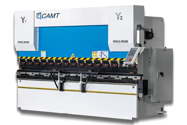
The minimum bend radius is the smallest inside radius a sheet metal part can be formed to without cracking on the outer surface of the bend. It is a property of the material — its grade, temper, thickness, grain direction and condition — long before it is a property of the machine. For common sheet metals the practical starting point sits between roughly 0.5 and 4 times the material thickness: about 1T for mild steel, 1.5T–2T for annealed 304 stainless, 1T–1.5T for 5052-H32 aluminum, and 2T–4T for 6061-T6 and high-strength steels. The deciding number, every time, is the forming data published for your exact grade, temper, thickness and product form — plus a test bend before the batch runs.
Before you commit a radius to a drawing or a die to the rack, five points carry most of the weight:
- The outer surface of the bend must stretch, and stretching capacity is what the material sells you. Higher elongation permits a tighter radius; higher strength generally means less elongation, so the minimum radius grows.
- Temper matters more than the alloy name. 6061 in the O temper bends like a different material than 6061-T6.
- In air bending, the inside radius floats at roughly one sixth of the V-die opening for mild steel — so the radius on your drawing silently dictates the tooling you must own.
- Charts disagree because they assume different things — grain direction, thickness range, edge condition, forming method. Two honest charts can both be right.
- A test bend on your material, your edges and your tooling outranks every published table.

Minimum Bend Radius Chart by Material
The table below provides preliminary design guidelines for common sheet metal materials. Values are typical shop starting points for a 90° air bend across the rolling grain, in otherwise clean conditions (deburred cut edges, room temperature, no coating failure in the bend zone). They are indicative ranges, not guaranteed forming limits — the data for your exact grade, temper and thickness decides production numbers.
| Material | Typical Minimum Inside Radius (R) | Key Bending Considerations |
|---|---|---|
| Mild steel, cold-rolled (low-carbon) | 0.6T–1T; design to 1T | Good formability; edge condition and grain matter only on the tightest radii |
| Hot-rolled steel | 1T–1.5T | Mill scale and cut-edge quality drive cracking more than the grade does |
| Stainless steel 304 / 316 (annealed) | 1.5T–2T | Work hardening and springback push practice toward the upper end |
| Aluminum 5052-H32 | 1T–1.5T | Good formability; temper is the lever; grain matters on tight bends |
| Aluminum 6061-T6 | 2T–4T | The upper end is the safer default; along-the-grain bends need more |
| Aluminum 3003-H14 | 0.5T–1T | Generally forgiving; marks easily on cosmetic faces |
| Galvanized steel | 1T–1.5T | Coating can flake or crack before the base metal fails |
| Copper (annealed) | 0.5T–1T | Ductile and forgiving; soft copper marks easily |
| Brass (half-hard) | 1T–1.5T | Temper governs; softer tempers tolerate tighter bends |
| High-strength and AHSS (HSLA to DP980) | 1.5T–4T or more | Grade, elongation and microstructure; martensitic grades can exceed this range |
Copper, brass and coated steels appear here for cross-reference; steel, stainless and aluminum are the families this article walks through in detail.
How to Use the Bend Radius Chart
The radius is measured on the inside of the bend, not the outside.
A 2 mm mild steel sheet designed with an inside radius of 1T:
R = 1 × 2 = 2 mm
The same thickness of 6061-T6 aluminum at a preliminary 3T:
R = 3 × 2 = 6 mm
The difference is significant. Applying the same tooling and radius to both materials may result in a successful steel bend and a cracked aluminum part — which is why material-specific radius selection belongs before the drawing is finalized and the tooling is ordered, not after the first scrap bin fills up.
Minimum Bend Radius for Mild Steel
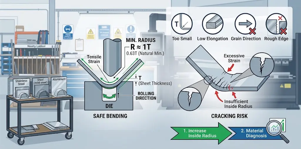
Mild steel is widely used in sheet metal fabrication because of its relatively good formability, availability and cost. Common applications include electrical cabinets and enclosures, machine frames and brackets, automotive components, structural sheet metal parts, and industrial equipment housings.
For low-carbon steel, a minimum inside radius of approximately 0.6T–1T is a sound preliminary guideline, and 1T is the usual design default. The natural minimum — the point below which the material “turns sharp” — sits near 0.63T for cold-rolled commercial quality, so a drawn radius of 0.5T is not a radius the material will actually form.
Even mild steel cracks when the inside radius is too small. The usual suspects are excessive tensile strain on the outside of the bend, a batch with lower elongation than expected, a bend line running parallel to the rolling direction, and rough or work-hardened cut edges inside the deformation zone. If cracking appears, increasing the inside radius is the first adjustment to consider — and if that does not explain it, the defect needs diagnosis rather than guesswork, which is the job of our sheet metal cracking at the bend line guide.
Minimum Bend Radius for Stainless Steel
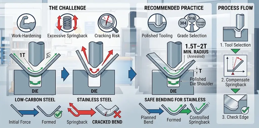
Stainless steel is more challenging to bend than most low-carbon steels because it work-hardens and springs back more. Common grades such as 304 and 316 are widely used in food processing equipment, medical and pharmaceutical equipment, chemical processing systems, enclosures, and architectural components.
For annealed 304 or 316, an initial inside radius of approximately 1.5T–2T is the realistic starting band. Work hardening is the mechanism behind both of stainless’s signature behaviors: as the material deforms, its resistance to further deformation rises, which means higher forming force, more springback, and cracking risk concentrated at tight radii. The bending program should account for springback rather than trusting the nominal bend angle — the compensation options are laid out in springback in sheet metal bending.
Tooling selection matters more than on carbon steel too: surface scratching and galling on stainless cosmetic faces often force polished or specialized tooling, and a dull die shoulder leaves its own defect. The grade-specific details — tonnage factors, grade selection, edge handling — are covered in bending stainless steel on a press brake.
Minimum Bend Radius for Aluminum
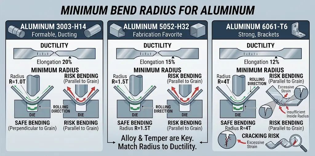
Aluminum is lightweight and widely used in aerospace, transportation, electronics and industrial enclosures, but its alloys bend nothing alike. The alloy and temper are often more important than the material name alone — and the ductility numbers behind them are worth reading directly. MatWeb’s typical data for 6061-T6 lists elongation at break around 12% for 1.6 mm sheet but around 17% for 12.7 mm bar of the same alloy and temper: same designation, different product form, different ductility, therefore a different minimum radius. The alloy name is a category, not a forming spec.
Aluminum 5052-H32
5052-H32 is commonly selected for sheet metal fabrication because of its good formability and corrosion resistance. A preliminary inside radius of 1T–1.5T suits most applications, depending on thickness and grain direction. Typical uses include electrical enclosures, marine components, equipment panels and lightweight brackets. When tight bends are required, bending perpendicular to the rolling direction offers better formability than bending parallel to it.
Aluminum 6061-T6
6061-T6 is stronger than 5052-H32 but markedly less suitable for tight-radius bending. Plan on 2T–4T as the working band, with the upper end the safer default and with-grain bends frequently needing more. The classic mistake is reusing the radius and tooling that worked for 5052-H32 — the result is visible cracks along the outside of the bend, especially when the bend runs parallel to the rolling direction.
If a design needs both strength and tight bends, change one of the levers rather than forcing the radius: a different alloy or temper, a larger radius, a controlled grain direction in the nest, or forming in a softer temper followed by heat treatment — an option that must be evaluated for the specific alloy and component. The decision ladder for each lever, and the parameter chain behind it, is walked through in how to bend aluminum without cracking.
Aluminum 3003-H14
3003-H14 offers good formability and suits enclosure, ducting and decorative work. A preliminary inside radius of 0.5T–1T is often acceptable, verified against the material specification and the actual bending conditions.
Why Bend Radius Charts Disagree — and How to Use One Anyway
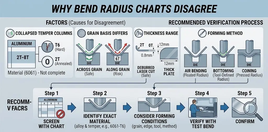
Search “minimum bend radius chart” and you will find one material quoted anywhere from 2T to 8T for 6061-T6. Most of that spread is real, and knowing where it comes from is what makes any chart usable:
- Temper columns get collapsed. “Aluminum 6061” without a temper is an incomplete spec; T4, T6 and O behave like different materials.
- Grain basis differs. A table that assumes across-grain bending lists lower values than one that assumes the worst case.
- Thickness range differs. Values collected from thin-gauge precision work do not transfer to plate.
- Edge condition differs. Charts built on deburred laser-cut edges run less conservative than those built on sheared edges with burrs.
- Forming method differs. Air bending, bottoming and coining strain the material differently, and a minimum radius for bottoming is a different question than the floated radius in air bending.
Given that, treat every chart — including the one above — as a screening tool that narrows the question, and let the verification steps below settle it.
How to Verify the Radius for Your Material
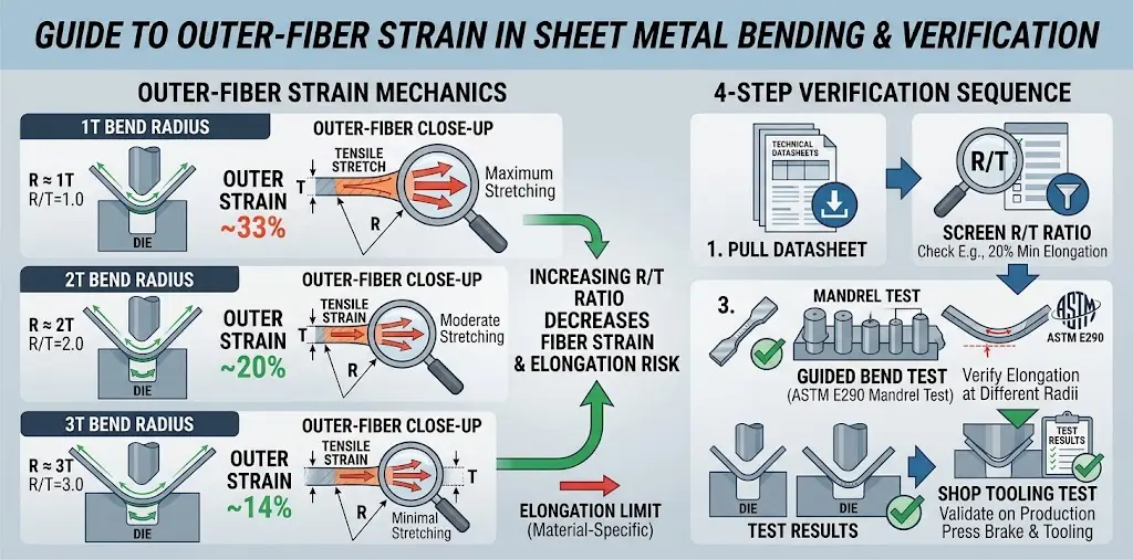
The strain demanded of the bend’s outer surface is set almost entirely by geometry: bend tighter relative to thickness and the outer fiber must stretch further. As a rough mid-thickness approximation, the outer-fiber strain runs near one third at an inside radius of 1T, near 20% at 2T, and near 14% at 3T. Whether that demand breaks the part depends on the supply side. WorldAutoSteel’s AHSS Guidelines state the relationship plainly — higher total elongation sustains a larger outer-fiber stretch and permits a smaller bend radius, while higher strength usually comes with lower elongation, so the minimum radius must increase as grades get stronger.
Two limits keep that logic from becoming a formula you can run on a calculator:
- Gauge-length mismatch. Tensile elongation is measured over a 50 or 80 mm gauge length; the bend zone stretches over a band a few millimeters wide, so dividing one number by the other is only a screen.
- Microstructure. In multiphase steels such as dual-phase and TRIP grades, shear fracture along hard-phase interfaces cuts bendability short of what total elongation predicts.
The honest verification sequence is short:
- Pull the forming data for the exact product. The mill’s datasheet for your sheet, not the alloy family brochure. Where bendability is a certified property, the product standard will say so — for aluminum sheet, ASTM B209 requires each alloy, temper and thickness to bend cold around a pin without cracking as a condition of certification.
- Screen the drawn radius against the r/t arithmetic to confirm the request is not absurd on its face.
- Run a guided bend test. ASTM E290 is the standard method: force a specimen around a defined radius or mandrel and examine the convex surface for cracks. It is the same judgment a shop test coupon makes, formalized.
- Prove it on your tooling with your edges. Three test bends across and with the grain, measured after the load comes off, tell you more than any chart — and they double as springback samples.
Thickness and V-Die Opening: The Chain Behind the Radius
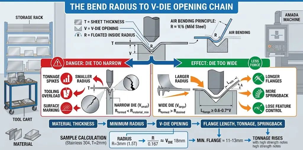
A minimum radius number only matters once it lands on a machine, and it never lands alone. Thickness sets the absolute size of the radius — a radius valid at 1 mm does not transfer to 6 mm of the same grade — and in air bending the V-die opening sets the radius the material actually forms.
For mild steel the practical relationship is R ≈ V/6 (about 0.16–0.17 × V). A 12 mm die therefore floats an inside radius of roughly 2 mm; stronger materials float a larger radius on the same die, so the exact fraction depends on what is in the brake. Reverse the logic and the drawn radius dictates the die: R ÷ 0.167 gives the V opening the job wants. The full selection logic, including the tonnage cost of narrow dies, is covered in how to choose a V-die opening.
From there the chain continues in both directions:
- A die that is too narrow produces a smaller radius but raises tonnage steeply, overloads tooling, marks the surface and — if the radius lands below the material’s minimum — cracks the part.
- A die that is too wide produces a larger radius with less force, but demands longer minimum flanges, opens up more springback and gives up control of small features.
The flange consequence is easy to underestimate: the shortest flange a die can support runs roughly 0.6–0.7 × V for a 90° air bend, so the die the radius demands also dictates the smallest flange the part can carry — the arithmetic lives in minimum flange length: how to calculate it. And because tonnage rises as the V narrows and as material strength climbs, a tight radius on high-strength steel is simultaneously a tooling load limits decision — the die in the rack may be rated well below the force the narrow opening demands.
A worked example ties the chain together. A 2 mm 304 stainless bracket with a drawn R3 inside radius (1.5T — legal for the material) needs a V around 18 mm, which prices into the tonnage formula at stainless’s higher material factor; the flange must clear about 11–13 mm; and the springback is larger than mild steel’s, so the angle after unloading will not be the angle under load. Every one of those numbers was decided the moment the radius went on the print.
Air Bending, Bottoming and Coining
The bending method changes both the achievable radius and the force applied to get it. In air bending — the default in modern CNC press brake work — the sheet touches the punch tip and two die shoulders, the angle comes from ram depth, and the radius floats at its natural fraction of the V opening. It is flexible on angles, tooling and material mix, and gentler on force.
Bottoming drives the material into closer conformity with the die, which can improve angle consistency under suitable conditions, at substantially higher force. Coining goes further still, and while it produces precise bends under controlled conditions, it should never be used to force a material into a radius smaller than its safe forming limit — excessive strain cracks the part no matter how much pressure is applied, and the load must be calculated against the machine rating and the die’s own load limit. The three methods, their trade-offs and where each belongs are compared in the sheet metal bending guide.
When the Part Cracks: Checks Before You Blame the Machine

If a part cracks during bending, changing the program alone rarely solves it. Five checks, in order:
- Confirm the grade and temper. Verify the actual material certificate. 5052-H32 and 6061-T6 obey different radius rules, and a substitution without a radius and tooling review is a common root cause.
- Check the rolling direction. For critical parts, specify grain direction on the drawing and nest the bend across the grain where the geometry allows.
- Increase the inside radius. Often the simplest solution when the design allows it — and the cheapest, because in air bending the die decides the radius anyway.
- Inspect the material edge. Burrs, laser-recast layers and sheared work-hardened edges are crack initiation points. If cracks consistently start at the edge, fix the edge preparation before touching anything else.
- Run a test bend. Form a sample with the actual material and tooling, inspect the outer bend surface, and measure radius and angle after the load comes off before releasing the batch.
When a crack survives all five checks — or when the pattern of where it starts is confusing — the diagnosis belongs to defect analysis, and our sheet metal cracking at the bend line guide walks through reading the crack itself. And where a tight cosmetic radius is genuinely non-negotiable, pre-grooving the bend line reduces the thickness the bend must form; V-grooving machines exist for exactly this class of work.
Choosing a Press Brake for Mixed Materials and Radii
The ability to achieve a required bend radius depends on the press brake, tooling and process control working together. Tonnage and bending length eliminate machines that cannot do the job; what separates the right machine from an adequate one for mixed-material shops is die inventory that matches the radii the prints demand, headroom for the narrow-die work that stainless and high-strength steels require, and angle control that absorbs their springback. A CNC control improves repeatability through programmable positioning and consistent sequences — but it cannot rescue an unsuitable radius, the wrong material or an overloaded die. The press brake range and the configurations that pair with this kind of work are laid out on our press brake machines page, and the clamping, storage and segmentation options that make multi-radius part mixes practical are covered under tooling and tool storage solutions.
Frequently Asked Questions
What is the minimum bend radius for 1 mm mild steel?
A preliminary inside radius of approximately 0.6–1 mm is a sound starting point, and 1 mm is the usual design default. The natural minimum for cold-rolled steel sits near 0.63 mm, so a drawn radius below that will not form as drawn. The production value depends on the grade, edge condition and tooling — verify with a test bend.
What is the minimum bend radius for 3 mm aluminum?
It depends on the alloy and temper. For 3 mm 5052-H32, plan around 3–4.5 mm (1T–1.5T). For 6061-T6, work in the 6–12 mm band (2T–4T), with the upper end the safer default and with-grain bends needing more. These are screening values; the mill’s data for the exact product decides.
Why does aluminum crack when bent?
Usually one of four things: an inside radius tighter than the temper tolerates, a bend running with the rolling grain, a rough or work-hardened cut edge inside the deformation zone, or a material substitution nobody re-reviewed. High-strength tempers such as 6061-T6 are the most common offenders in fab shops.
Does a larger bend radius reduce cracking?
Generally yes — a larger inside radius lowers the strain on the outer surface, which is why increasing the radius is the first lever in every crack investigation. The radius still has to meet the part’s functional requirements, which is why the levers in the aluminum and verification sections exist.
Can a press brake bend metal to a zero-radius corner?
Not by air bending — every material has a natural minimum radius below which it will not form, whatever the punch nose says. A closed hem is a different operation: the bend is folded flat with dedicated tooling, and even then several alloys crack in closed hems. Our how to hem sheet metal on a press brake guide covers what hems can and cannot do.
How do I verify the minimum radius for my specific batch?
Pull the forming data for the exact grade, temper and thickness, screen the drawn radius against the r/t arithmetic, then run a guided bend test per ASTM E290 — or its shop equivalent, a measured test coupon on production tooling — before releasing the job.
Conclusion
Selecting the correct minimum bend radius by material is essential for producing reliable sheet metal components. Mild steel, stainless steel, aluminum, copper and high-strength alloys all have different forming characteristics; a radius that works for one material may crack or distort another. Temper, grain direction, thickness and edge condition move the number as much as the alloy name does, and in air bending the radius you draw silently selects the die, the flange and the tonnage.
Before production: confirm the material certificate, screen the radius, check the tooling chain, and prove the job with a test bend.
Need a press brake solution for your sheet metal production? Contact CAMT to discuss your material range, bending length, thickness and tooling requirements.