Every fiber laser quotation, cutting test and quality discussion runs on four words: kerf, heat-affected zone (HAZ), focus position and assist gas. They are not jargon for its own sake. Kerf decides how many parts you can nest on a sheet. HAZ decides whether the edge survives bending, welding and coating. Focus position decides where the beam’s energy actually lands. Assist gas decides both the edge finish and a large share of your running cost. And when parts come off the machine with wrong dimensions, heavy dross, discolored edges or results that drift between shifts, one of these four terms is usually where the answer lives.
This guide explains each term the way it comes up in a real purchase decision, shows how the four interact, and ends with a checklist you can use at your next cutting test. The fiber laser cutting machines behind all four terms — open-type, enclosed exchange-table and pipe models — are covered separately, because the terms below apply to every one of them.

Kerf: The Slot the Beam Actually Cuts
What Is Kerf Width?
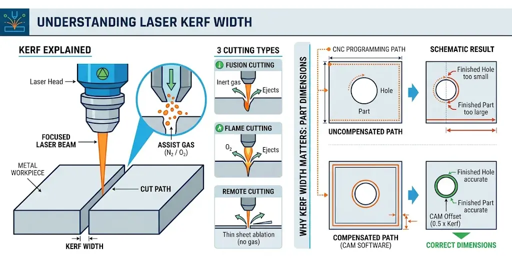
The kerf is the gap the laser leaves behind. Strictly, the focused beam melts a localized channel and a co-axial gas jet ejects the molten material, creating the kerf as the head moves along the programmed path. TWI’s process notes distinguish three ways this happens: in fusion cutting the inert jet simply pushes metal out; in flame cutting the oxygen jet also feeds an exothermic reaction that adds energy; in remote cutting a thin sheet is partially ablated with no assist gas at all.
Laser cutting produces much narrower slots than most conventional thermal processes, but the width is not zero — and that residual width is where the practical questions begin.
Why Kerf Width Matters
Kerf width directly affects part dimensions. When cutting a circular hole, the beam removes material along the path; if the CNC program does not compensate for it, the finished hole lands off dimension, with the error direction depending on whether the toolpath runs the internal or external contour.
This is handled in software, not ignored: nesting and CAM programs offset the toolpath by roughly half the kerf so the finished part lands on size. The compensation value is part of machine calibration, which is why it belongs on the agenda when a technician commissions your machine — and why a machine whose kerf drifts between jobs will quietly produce parts that drift with it.
Kerf also sets design limits. Very tight internal corners and very narrow slots are bounded by the beam’s spot size and the kerf it cuts. If your drawings contain both fine slots and heavy plate, say so before the demo, because that combination stresses the process window more than either feature alone.
What Affects Kerf Width?
| Factor | Effect on Kerf Width |
|---|---|
| Cutting speed | Slower travel widens the kerf; faster travel narrows it. A narrow kerf packs more parts per sheet but shrinks the channel the gas must flush. |
| Focus position | Sets the beam diameter and energy distribution through the thickness — and with them the kerf profile and taper. |
| Laser power | Higher power can widen the slot if speed and gas are not adjusted to match. |
| Beam quality | A better beam focuses into a smaller, more concentrated spot. |
| Material thickness | Thicker stock generally produces a wider or more tapered kerf and reacts more strongly to parameter drift. |
| Assist gas pressure | Shapes molten-material removal and therefore kerf geometry. |
| Nozzle condition | A damaged or contaminated nozzle disrupts gas flow and produces inconsistent cuts. |
No single parameter decides the outcome. Slower travel, for example, also widens the kerf’s flushing problem: as the channel narrows, the assist gas loses part of its scouring power, which is why kerf, gas flow and cutting speed have to be tuned together rather than optimized one at a time.
How to Reduce Kerf-Related Dimensional Errors
If finished parts consistently differ from their programmed dimensions:
- Verify the kerf compensation value against the material and thickness actually being cut.
- Check the focal position — an incorrect focus changes the kerf profile and causes taper.
- Inspect the nozzle: clean, undamaged, correctly centered on the beam.
- Compare power, speed, gas pressure and stand-off against the recommended cutting conditions.
- Measure real test cuts and re-verify compensation before committing a production batch.
These checks matter most on small holes, narrow slots, interlocking parts and anything with tight assembly tolerances. For the measurement methods and compensation workflow in detail, see Kerf Width in Laser Cutting: What It Is and How to Compensate.
Heat-Affected Zone (HAZ): What the Heat Leaves Behind
What Is the Heat-Affected Zone?
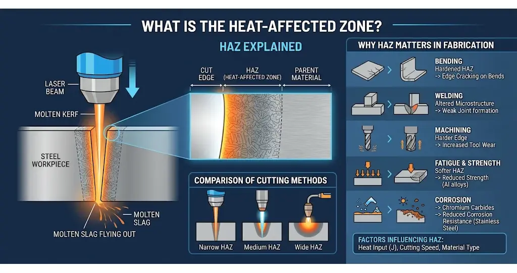
Laser cutting is a thermal process, and heat does not stop at the cut line. The heat-affected zone is the band of parent metal next to the edge that did not melt but whose microstructure and mechanical properties were altered by the heat. TWI, the UK-based welding institute, defines the HAZ as the non-melted area whose material properties change as a result of exposure to high temperatures from welding or high-heat cutting.
The good news is that laser cutting concentrates heat into a very small area, so its HAZ is small compared with plasma or oxy-fuel cutting. The honest news is that it is not zero, and its size follows predictable rules: more heat input and slower cutting enlarge it; materials that conduct heat away quickly shrink it.
Why HAZ Matters in Fabrication
The HAZ rarely shows in a visual inspection, but it decides how the edge behaves in the next process:
- Bending: in some steels the HAZ is harder than the parent material, which can promote edge cracking on tighter radii.
- Welding: altered microstructure and residual stress near the edge influence how the joint forms.
- Machining: a hardened edge increases tool wear in drilling or milling.
- Fatigue and load-bearing parts: in precipitation-hardened aluminum alloys the HAZ is softer and weaker than the parent metal, which matters if the part carries loads near the cut edge.
- Corrosion service: in stainless steel, high edge temperatures can cause sensitization — chromium carbides precipitating at grain boundaries — reducing corrosion resistance at the very edge you may be selling as “stainless.”
- Finishing: oxidation and heat tint may require cleaning before painting or coating.
None of these are reasons to avoid laser cutting. They are reasons to state your downstream processes when you request a cutting sample, so the sample is produced with the gas and speed your real parts will need. Edge appearance, hardness and corrosion behavior connect to acceptance criteria in ISO 9013 Explained: Specifying Laser-Cut Edge Quality.
What Makes HAZ Worse — and How to Minimize It
The drivers are the same ones that shape the kerf: cutting speed, power, focus and gas. Cutting too slowly extends heat exposure; excess power pours in energy the cut does not need; a misplaced focus spreads energy instead of concentrating it; a mismatched gas evacuates molten metal inefficiently and lets heat soak. Minimizing HAZ therefore does not require a new playbook — it requires the process window those parameters define to be respected:
- Match power to thickness instead of defaulting to maximum.
- Keep speed inside the stable cutting range — faster is not automatically cooler, because an unstable cut heats the edge in its own way.
- Hold the correct focal position (next section).
- Keep the optical path clean, because a dirty protective window scatters energy and destabilizes the cut front.
For demanding applications, a consistent process beats a fast one: the edge that bends and welds cleanly on part 500 was produced by the same settings as part 1.
Focus Position: Where the Beam Does Its Work
What Is Focal Position? Zero, Positive and Negative
The cutting head’s lens concentrates the beam into a spot, and the position of that spot relative to the sheet is the focus position. It is expressed against the upper surface: zero focus puts the spot at the surface, positive focus above it, negative focus inside the material.
Two optical facts govern it. A smaller focused spot gives higher power density, but the depth of focus — the distance over which the spot stays useably small — shrinks with it. TWI’s notes describe the trade-off directly: a short focal length yields a small spot and a shallow depth of focus; a longer focal length buys depth at the cost of spot size, and thicker material needs that depth. There is no universal focus setting for every material and thickness.

How Focus Changes With Gas and Thickness
The assist gas changes where the spot belongs, because each gas supports a different reaction. Focus position rules differ for oxygen and nitrogen cutting, and the differences are specific:
- Oxygen (flame cutting). The reaction adds heat, so moderate power density near the surface is enough. Focus typically sits at or just into the top surface, or slightly above it on thick plate.
- Nitrogen (fusion cutting). The inert jet contributes no heat; the beam alone must melt the metal all the way down. Focus therefore goes at or just below the bottom of the sheet, keeping enough energy density deep in the kerf to push molten metal out cleanly. Because the focus rides the bottom surface, nitrogen cutting is the most thickness-dependent of the three.
- Compressed air. Air is mostly nitrogen with enough oxygen to add a smaller secondary reaction, and it generally performs best with the focus near the middle of the thickness.
On modern fiber laser heads this is handled by autofocus: the operator selects material and thickness and the head moves its optics accordingly, with no lens swap mid-shift. Older or simpler setups use interchangeable focusing lenses, which works but adds a human step — and a human error opportunity — to every job change. When you compare machines, ask not only whether autofocus is present but how the focus zero point is calibrated and verified after service, because every other focal position inherits that zero.
What Wrong Focus Looks Like
| Focus Condition | Possible Cutting Problem |
|---|---|
| Focus too high | Excessive top kerf width, poor energy distribution through the thickness, unsuitable cut profile |
| Focus too low | Excessive bottom kerf width, poor melt ejection, increased dross in some conditions |
| Unstable focus | Kerf geometry drifts, cut quality changes between parts |
| Wrong focus for thickness | Incomplete cuts, rough edges, excessive taper |
Symptoms overlap between causes, so read the full cut cross-section rather than judging from one surface.
How to Adjust Focus Systematically
- Start from the recommended setting for the material, thickness and gas.
- Inspect the focusing lens and protective window for contamination or damage.
- Confirm the head holds consistent stand-off from the surface.
- Verify nozzle centering against the beam.
- Move the focus in small steps and judge each change on the cut cross-section.
- Record the winning setting for repeat jobs.
Focus interacts with consumables as much as with settings: a damaged protective lens scatters the beam before it reaches the focal point, and a worn nozzle distorts the gas flow that must match it. Both are inexpensive parts, and keeping them in condition is the cheapest cut-quality investment in the shop — the full range of laser cutting consumables and spare parts exists for exactly this reason.
Assist Gas: Oxygen, Nitrogen or Compressed Air
What the Assist Gas Does
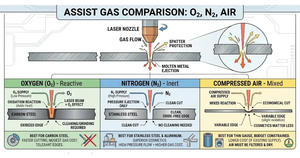
Delivered through the nozzle into the cut zone, the assist gas does three jobs at once: it ejects molten metal from the kerf, it protects the focus lens from spatter, and — depending on the gas — it either adds energy to the cut or stays out of the way. That third job is what separates the three common choices.
Oxygen Cutting (O₂)
Oxygen is a reactive gas used mainly on carbon steel. The oxidation reaction with the iron releases extra heat, so the beam and the chemistry share the work — which is why oxygen cutting runs at modest pressures and flows. The trade-off is the edge itself: an oxidized surface that usually needs cleaning or grinding before painting, coating or welding. Oxygen suits shops cutting carbon steel where the application tolerates that edge or the post-treatment is planned anyway.
Nitrogen Cutting (N₂)
Nitrogen is inert: it adds no heat and does its work by pressure alone, driving molten metal out of the kerf to leave a clean, oxide-free edge. That is why it is the default for stainless steel, aluminum and any visible-surface or food-equipment work. The cost follows from the physics — evacuating metal by brute force demands far higher pressure and flow than oxygen ever needs, and sustained over a shift, that flow is where the gas bill lives. Supply and purity need managing as carefully as the beam.
Compressed Air Cutting
Compressed air — roughly 78% nitrogen and 21% oxygen — is not chemically inert: it cuts mostly like nitrogen with a smaller oxygen reaction working alongside. Its appeal is cost, especially where an air supply already exists. Its limits are the edge, which can show oxidation, and the air itself: moisture, oil and contaminants travel straight into the cut and the optics, so filtration and drying are not optional. Air fits thin-gauge work where edge cosmetics matter less and the budget rules.
Which Gas Should You Choose?
| Oxygen (O₂) | Nitrogen (N₂) | Compressed Air | |
|---|---|---|---|
| Gas behavior | Reactive — adds heat | Inert — adds no heat | Mostly inert, small oxygen reaction |
| Common application | Carbon steel | Stainless steel, aluminum, bright-edge work | Thin sheet, cost-driven work |
| Edge result | Dark, oxidized — post-treatment usual | Clean, oxide-free, finishing-ready | Acceptable with possible oxidation |
| Typical pressure | Relatively low | Relatively high | Application-dependent |
| Gas cost driver | Low flow | High flow dominates running cost | Lowest, if air system exists |
The decision should not be made on gas price alone. Work through six questions: material and thickness; whether the part truly needs an oxide-free edge; whether it will be welded, painted or coated; the speed and volume the job requires; and the total gas consumption per shift — not per cubic meter. Nitrogen may cost more per unit yet still win the job by deleting a cleaning operation downstream. Gas strategy is also a machine configuration question, not an afterthought: plumbing, regulator capacity and head flow control are sized when the machine is specified, so a production mix that leans toward bright stainless edges should confirm the nitrogen supply path — bottles, bulk tank or on-site generation — with the same seriousness as the resonator. The gas-by-gas comparison continues in Laser Cutting Assist Gas: Oxygen vs Nitrogen vs Compressed Air.
How the Four Terms Interact
The four terms are not independent facts to memorize; they form a loop. Focus position sets the spot size and where its energy lands, which shapes the kerf. The kerf is the channel the assist gas must flush, so kerf width constrains gas dynamics. Gas choice feeds back into focus position. And all three, through total heat input, decide the HAZ you will bend, weld and coat later. That is also why the same factor table keeps reappearing across sections — speed, power, focus and gas are the shared levers of all four terms.
| Term | What it mainly decides | First check when quality drifts |
|---|---|---|
| Kerf | Nesting yield, part dimensions, minimum slot/corner size | Has the compensation value been re-verified after service? |
| HAZ | Bending and welding behavior at the edge, corrosion resistance | Is the edge oxidized because the gas drifted, not the material? |
| Focus position | Energy density where the work happens; dross and top-edge quality | When was the focus zero last verified against a slit test? |
| Assist gas | Edge finish, cutting speed window, running cost | Does supply pressure hold through a full nest, not just the first cut? |
From Vocabulary to Verification: The Cutting Test and the Single-Variable Rule
Four Sentences to Put on the Table at a Cutting Test
A cutting test is where vocabulary becomes acceptance criteria. Before the sample is cut, state four things:
- Material and thickness in production form — the actual alloy and gauge, not the catalog’s easiest one.
- Edge requirement — bright and oxide-free for nitrogen, or is an oxygen edge acceptable with deburring? This single sentence selects the gas, the focus strategy and the gas cost line in the quotation.
- Smallest feature — the tightest slot and smallest hole you regularly cut, so the kerf and spot-size limits are tested, not discovered after delivery.
- Downstream process — bending, welding, coating or food-service use, which is where HAZ behavior either stays invisible or becomes a field failure.
Then inspect the sample against those sentences: measure a dimension that crosses the kerf, read the bottom edge for dross, check whether the top edge rounding matches the focus story you were told, and note the edge color on stainless. A supplier who welcomes this checklist is telling you something useful about their process support.
Troubleshooting Without Guesswork: Change One Thing at a Time
Consider a shop cutting 6 mm stainless whose parts suddenly show dross, rough edges and drifting dimensions. Changing the laser power alone rarely fixes it, because the real cause may sit anywhere in the loop above — a focal position that no longer suits the kerf, nitrogen pressure that sagged, a worn nozzle, a speed that no longer matches the power, or a kerf compensation value nobody re-checked. A few examples of how the terms map to symptoms:
| Symptom | Terms to check first |
|---|---|
| Parts consistently over- or undersized | Kerf compensation value vs. measured kerf |
| Heavy dross on the bottom edge | Focus position, gas pressure, nozzle condition, speed |
| Oxidized edges on stainless | Gas selection and purity vs. edge requirement |
The reliable method is to change one parameter at a time and inspect the full cut cross-section after each change: confirm material and thickness; check the cutting head (protective window, lens, nozzle, centering, height control); verify the gas (type, purity, pressure, supply stability); compare power, speed, focus, nozzle diameter and stand-off against recommended settings; then record the winning combination — material, thickness, gas, pressure, nozzle, focus, power, speed — so the job repeats without rediscovery. Deep diagnosis of dross types, burrs and striations belongs to the full troubleshooting discipline covered in Fiber Laser Cutting Troubleshooting: Dross, Burrs and Rough Edges.
Where CAMT Fits
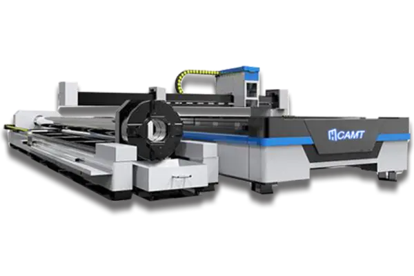
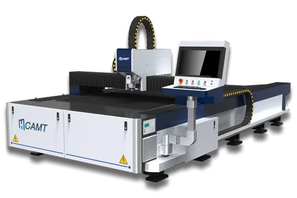
CAMT builds fiber laser cutting machines across the three common shop profiles. The ULE enclosed exchange-table series is aimed at batch sheet-metal production, where shuttle tables keep the beam cutting while operators unload on the other side. The ULF open-type desktop series gives small and mid-size workshops a lower-cost entry with flexible loading. For tube and profile work, the ULT pipe laser adds chuck rotation and bevel cutting on the same process principles described above. How these machines work, part by part, is laid out in What Is a Fiber Laser Cutting Machine and How Does It Work?, and matching a configuration to your materials and volumes is the subject of How to Choose a Fiber Laser Cutting Machine: Complete Buyer’s Guide.
More important than any single model is what happens after the machine ships: cutting tests on your material before you commit, installation with focus calibration verified on your floor, and technical support that treats kerf, focus and gas as service items, not sales talking points. If you are building a vocabulary before buying, these are the people who should be answering the questions this article raises — contact CAMT with your material list and edge requirements, and ask for a cutting test built around them.
The terms keep working after delivery, too. Nozzles and protective lenses are consumables with a direct line to focus stability; the head itself rewards a short weekly routine; the whole machine runs on a maintenance rhythm that protects the accuracy this article has been about. We cover the head and its lens in How to Maintain a Fiber Laser Cutting Head and Protect Its Lens, and the machine-wide routine in Fiber Laser Cutting Machine Maintenance: A Practical Checklist.
FAQs: Laser Cutting Terms Explained: Kerf, HAZ, Focus and Assist Gas
What Is the Difference Between Kerf and Cut Width?
They generally refer to the same thing — the width of material removed during cutting. “Kerf” is the standard term in laser cutting and CNC programming, which is why compensation settings are labeled with it.
What Is a Typical Laser Cutting Kerf Width?
There is no universal value. Kerf width varies with material, thickness, focus position, cutting speed, power and gas conditions, so quoting one number for every machine would be misleading. For production, measure the actual kerf under your intended cutting conditions and use that measured value for CNC compensation.
Is the Heat-Affected Zone Always a Problem?
No — but it is never zero, either. A thin altered band always exists because laser cutting is a thermal process. Whether it becomes a problem depends on the material and the next operation: bending tight radii, welding, machining or corrosion service all raise the stakes, while parts that go straight into assembly may never notice it. State the downstream process and let the cutting parameters answer.
Why Does the Focus Position Change With Material Thickness?
Different thicknesses need different energy distributions through the cutting depth. The focal position controls where power density peaks, which shapes the kerf and the melt ejection — and the assist gas moves the ideal position again, since nitrogen cutting focuses near the bottom of the sheet while oxygen cutting focuses near the surface.
Which Assist Gas Is Best for Fiber Laser Cutting?
None is best universally. Oxygen suits carbon steel when an oxidized edge is acceptable; nitrogen is the choice where clean, oxide-free edges are required; compressed air is a cost-effective option for suitable thin materials. The right answer weighs edge quality, cutting speed, gas consumption and post-processing together.
Does Higher Laser Power Always Improve Cutting Quality?
No. Higher power expands the process window and raises available speed, but power that is not matched with speed, focus, gas and thickness simply widens the kerf, enlarges the HAZ and destabilizes the cut. Configuration should follow your actual material mix, not the biggest number on the spec sheet.
Conclusion: Better Understanding Leads to Better Cutting Results
Kerf, HAZ, focus and assist gas are more than vocabulary. They determine dimensional accuracy, edge quality, material utilization and the running cost behind every quotation line. Understanding how they interact lets you read a cutting chart critically, ask a supplier the questions that matter, and turn a cutting test into acceptance criteria instead of a demonstration.
And when you are ready to put the vocabulary to work on a machine, CAMT can help you identify a configuration suited to your materials, edge requirements and production mix — explore the CAMT fiber laser range or talk to our technical team about a cutting test built around your own parts.