In fiber laser cutting, even a small difference in kerf width can cause significant dimensional errors, especially when manufacturing precision sheet metal components, interlocking parts, and assemblies with tight tolerances. These problems often occur when kerf compensation is missing, incorrectly configured, or based on outdated cutting parameters.
Understanding kerf width in laser cutting helps manufacturers maintain dimensional accuracy, reduce material waste, and improve assembly consistency. This guide explains what kerf width is, what affects it, how to measure it, and how to apply the correct kerf compensation in your laser cutting workflow.

What actually moves the kerf
Every factor below changes k. What decides your day is whether it changes k without changing your program.
| Factor | How it moves k | Invalidates a stored offset? |
|---|---|---|
| Laser power | More energy per unit length widens the melt | Only if speed, focus or gas moved too |
| Cutting speed | Slower travel widens the slot; too fast under-cuts | Yes — speed is part of the datum |
| Material and thickness | Alloy, conductivity and thickness change absorption | Yes, always |
| Focus position | Sets spot diameter and waist depth | Yes — a new zero voids everything inherited |
| Nozzle and assist gas | Nozzle ID, centring and pressure govern ejection | Yes |
| Motion and structure | Acceleration and axis calibration move the contour, not the slot | No — and it still puts your part out |
The last row is the one people miss: a machine can hold a straight line true and still drift around a small circle, because the axes never reach steady velocity. That is a motion problem wearing a dimension’s clothes, and no kerf value removes it.
Parameter values belong to Fiber Laser Cutting Parameters: Speed, Power, Focus and Gas. What follows is what to do about that slot.
Before you touch the offset: sort the error
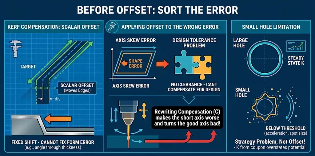
Kerf compensation is a scalar: it shifts a cut edge sideways by a fixed distance. It cannot change the shape of the cut through the thickness, the position of the machine axes, or the clearance your assembly was designed with. Most dimensional complaints are not a missing offset; they are an offset applied to the wrong kind of error.
| What you see | Error type | Can C fix it? | What actually fixes it |
|---|---|---|---|
| Profile small and hole large, same amount every part | Uniform centre-line bias | Yes | Measure k, set C = k/2, re-cut |
| Parts drift across a shift, or after a nozzle, gas or material change | The kerf moved | No — re-measure | Restore machine state: nozzle, window, focus zero, gas, height control |
| Top and bottom measure differently | Taper | No | Focus, gas, speed, perpendicularity; put permitted taper in the acceptance criterion |
| One axis only, or error grows with part length | Axis calibration or thermal displacement | No | Calibration and cut sequencing |
| Parts to print but will not assemble | Fit and tolerance stack | No | Clearance on the drawing, then an assembly trial |
The fourth row is where offsets go to die. If a part comes out 0.15 mm long on one axis and true on the other, rewriting C makes the short axis worse and turns the good axis bad.
Small holes need their own warning: below a diameter set by spot size and acceleration, the cut never reaches steady state, so a k from a generous coupon overstates what the hole can achieve. That is a strategy problem, not an offset problem.
Measure your own kerf
Your number comes from a coupon cut with compensation off, at production settings, on a blank from the same sheet — not a plate already through the machine, whose thermal state has changed.
Put five features on it: an outside square, a round hole, a narrow slot, a sharp corner, and a comb of n parallel cuts spanning a known length L. Cut with the compensation field at zero and nothing else changed.
k₁ = W_nom − W_out · k₂ = D_hole − D_nom · k = (k₁ + k₂) / 2 · C = k / 2
Averaging two independent estimates is the point. If |k₁ − k₂| exceeds your uncertainty, that gap is information: something other than a uniform bias is at work.
Say which of two quantities you measured. Slot width taken directly is biased by edge roughness and taper; width inferred from a part is biased by axis error and thermal contraction. Same number, different errors — the record must say which, or the next shift cannot reproduce it.
The comb covers the case where your instrument is not good enough — measure the remaining material as L_rem:
k = (L_nom − L_rem) / n
You have stretched n kerfs into one long reading while instrument uncertainty stayed constant, so uncertainty per kerf falls by about n. That matters because C is often smaller than the resolution people verify it with. ISO 14253-1:2017 sets the decision rules for proving conformity when a measured value sits near a limit with uncertainty accounted for. George Schuetz of Mahr Inc., writing in Modern Machine Shop, gives the shop-floor version: only by determining the uncertainty of the inspection system do you know what part of the tolerance band is left for production. When C and that uncertainty are the same order of magnitude, editing the offset on one caliper reading is editing noise.
Then record the coupon, not just the number:

| Field | Why it belongs in the record |
|---|---|
| Grade, heat or lot, measured thickness | The kerf belongs to this stock, not to "3 mm steel" |
| Gas, nozzle ID and condition, window status, focus zero and its date | These move k with no program change |
| Machine, controller, program version | Programs are not portable |
| k₁, k₂, top and bottom, taper, and which quantity was measured | The diagnosis, not the result |
| Instrument, coupon ID, C before and after, approver | Lets the next shift judge whether a change is real |
Correct kerf compensation toward scrap ensures exact part dimensions
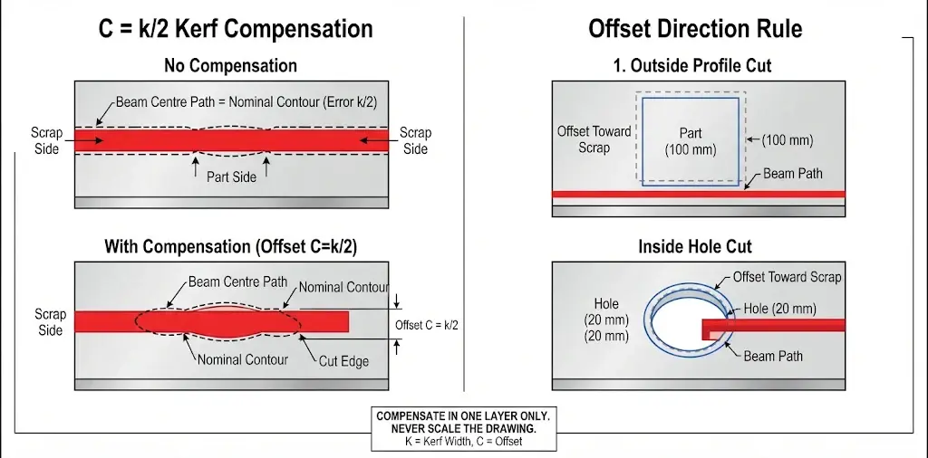
C = k / 2 shifts the beam-centre path sideways so the cut edge, not the beam centre, lands on the nominal contour.
One rule covers both contour types: offset toward the scrap side. Outside material becomes scrap when the path moves outward; material inside a hole becomes scrap when it moves inward.
At k = 0.2 mm, C = 0.1 mm: the 100 mm profile measures 100 mm, the 20 mm hole measures 20 mm. If the part is still 0.2 mm off, the offset never took effect — check the layer before doubling the value.
Know whether your software wants k or C. Some CAM and controller fields take the full kerf width and offset by half internally. Others take the offset itself. Enter C where k is expected and your correction halves; enter k where C is expected and it doubles. The symptom is a part that moves in the right direction by the wrong amount, which reads like a machine fault and is not. One coupon settles it.
Two rules keep the value stable:
- Compensate in one layer only. Nesting software, the CAM post and many controllers can all apply an offset. Pick one and disable the others. A DXF drawn at nominal size that is also pre-offset in CAD is corrected twice — the classic “we fixed the drawing and it got worse”.
- Never scale the drawing. Scaling changes every dimension proportionally and breaks mating features; an offset changes each contour by a fixed distance. Note in the program header which layer carries the offset, because a job moved to a second machine is otherwise a guess.
A single offset cannot fix varying top and bottom kerf taper widths
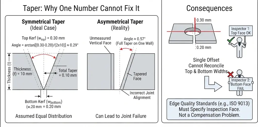
Measure top and bottom separately on plate thicker than a few millimetres and you will often find two different widths. Take a top kerf of 0.30 mm and a bottom of 0.20 mm on 10 mm plate:
per-wall angle = arctan[(w_top − w_bottom) / (2 × t)] = arctan[(0.30 − 0.20) / (2 × 10)] ≈ 0.29°
That formula assumes a symmetrical section, with the beam axis parallel to the cut face and the taper shared equally by both walls. If the taper sits on one wall only, that wall slopes at about 0.57°, not 0.29°, and a joint along the full thickness fails on the side nobody measured.
Two consequences follow. No single scalar reconciles 0.30 and 0.20: whatever C you enter, one face is right and the other wrong. And if the drawing does not say which face is inspected, two inspectors can pass and fail the same part.
A 2025 study on SS201 stainless cut with oxygen treated top kerf width, bottom kerf width and kerf taper as three separate responses and found different parameters dominated each (Zabon, Abbas & Bedan, Advances in Science and Technology Research Journal). One alloy, one gas, one matrix — not a ranking for your machine. The geometry is the point: a single offset cannot make two widths agree. Edge quality classes belong in ISO 9013 Explained: Specifying Laser-Cut Edge Quality, not in the compensation field.
Common-line cutting creates a conflict where each shared edge is C short

Two adjacent parts share a straight edge. For the left part, that edge is an outside profile on its right, so its toolpath shifts +C. For the right part, the same edge is an outside profile on its left, so its toolpath shifts −C. Two correctly compensated paths are therefore k apart. A single shared cut removes k centred on the line and leaves each part C short on that edge.
There are three honest options:
- Drop the common line. Two compensated paths: one kerf of extra material, both parts on size.
- Keep it and design for it. Accept −C on both shared edges, state which face the inspector measures from, put it on the drawing.
- Pre-offset that contour in CAD and switch compensation off for it. One layer, flagged in the header, or you have built the double-compensation failure into the nest.
Tim Heston’s 2026 nesting overview in The FABRICATOR reports that on thin material the benefit of common-line cutting has fallen while its risks have risen, and quotes Hexagon’s Doug Wood on fixing problems in the program, not at the control. Lindsay Luminoso’s 2025 survey in Canadian Metalworking confirms that nesting software sets kerf per material and thickness, adjusts toolpaths automatically, and must leave room for lead-ins, lead-outs and thermal limits. The working rule: gap ≥ k + lead-in and lead-out space + your own margin.
Joint fit runs on the same arithmetic. A tab and slot drawn to the same nominal width, uncompensated, has free play of (S_nom + k) − (T_nom − k) = g + 2k, where g is the clearance you designed. Correct compensation removes the 2k and leaves g. Keep g on the drawing; bury it in C and a change of thickness silently rewrites your fit. A tab on a gauging edge can also foul a backgauge finger on the press brake, so keep tabs off datum edges.
8. From drawing to released batch: the first-article routine

- Draw at finished size with the assembly clearance stated; do not pre-offset geometry the CAM will offset again.
- Freeze the conditions: material lot, measured thickness, gas, nozzle, focus zero, speed, power. Change nothing else during the trial.
- Zero the compensation in exactly one layer and cut the section 4 coupon on an adjacent blank from the production sheet.
- Compute k₁, k₂ and k. If they disagree beyond your uncertainty, return to section 3 before entering anything.
- Enter C = k/2, confirm from the field label whether the software wanted k or C, note both in the header.
- Cut a second coupon at the same settings, then measure top and bottom.
- Check the six things that decide acceptance: outside dimensions, hole diameters, slot widths, edge quality, taper, assembly fit.
- Retain both coupons, the record and the approved value. Release only after the second coupon passes.
If the re-cut still misses, do not increase C. A second correction stacked on a misdiagnosed error turns a good offset bad.
Re-run it on events, not a calendar: a new lot or grade, a new nominal thickness, a gas or nozzle change, a window replacement, head service, focus re-calibration, a different machine, or drift inside one shift. A kerf that moves is a maintenance signal first, and what catches it is usually consumables and calibration rather than the controller. Nozzles, windows and ceramics with traceable part numbers make that comparison possible; planned service and calibration is where focus zero and head alignment are re-established; software and control support covers which cut chart version ships with the machine. Operator training on trial cuts, measurement and offset changes is what lets the routine survive a change of personnel.
Choosing the machine, and what to demand in writing
What a machine has to deliver is a cut that stays put: stable delivered power, a repeatable focus zero, clean gas, and motion that holds position across a long nest. The compensation value stays your own process data; no supplier can quote it, and no machine removes the need to re-measure after a nozzle change.
Compare configurations on positioning accuracy and repeatability first, then focus control, parameter versioning in CNC and CAM, gas stability at the nozzle, and who can diagnose a drift.
Positioning accuracy and part accuracy are different quantities. A machine can position within a tight band and still cut outside tolerance, because kerf, taper, thermal growth and measurement sit between the axis and the finished edge. Read the model sheet for the configuration and its revision date; expect part tolerance to come from first article.
Settle ownership of that data at quotation. Fill the left column; require the right in writing.
| You supply | Supplier confirms in writing |
|---|---|
| Grade, lot practice, thickness band | Trial-cut protocol, and what the retained coupon must show |
| Part families, fit classes, datums | Which layer applies the offset: CAD, CAM post or control |
| Whether common-line cutting is used | How shared edges are handled, and where the −C is documented |
| Inspection method and its uncertainty | Who re-establishes focus zero after head service |
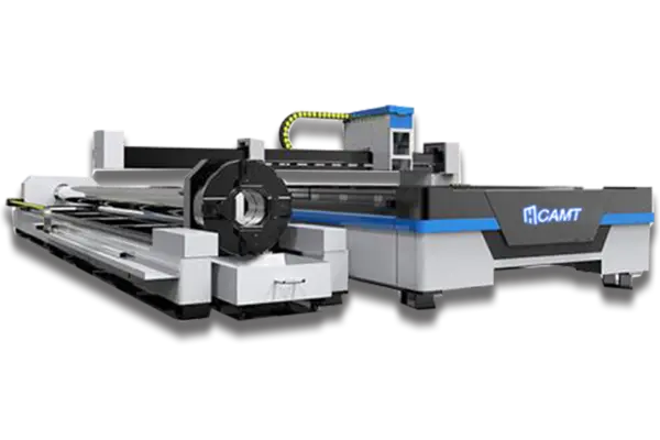
At CAMT (Nanjing Huameng Machinery Technology Co., Ltd.) the fiber laser cutting machine range covers three architectures that demand different things of a cut chart: the open-type ULF single-table machine for mixed work, the enclosed ULE with twin exchange tables for continuous production, the ULT plate-and-tube platform for profiles. Those are configuration descriptions, not accuracy guarantees. Remote diagnostics reconstruct a drifting kerf from logs, consumable history and parameter versions; the wider service scope sets out what is maintained, by whom and at what interval.
We will not claim a machine eliminates trial cuts, publish a universal kerf width, or assert compliance with any inspection standard on your behalf; that is established on your parts and signed off between your quality function and your supplier. Send your grade, thickness band, gas and current coupon record and we will structure the trial around the fit your process needs.