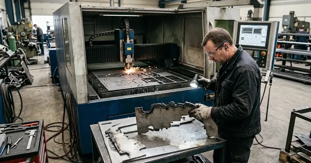
A fiber laser can cut cleanly for a whole shift and then hand you a batch nobody wants to touch: a crust of re-solidified metal under every part, burrs that must be ground off before blanks move on, or striations deep enough to reject. Nobody changed the program.
Almost every such defect is decided in the last fraction of a millimetre of the cut, at the exit point. The beam creates the melt; the assist gas removes it. When the two stop agreeing, the surplus lands on your part — as dross, as a burr, or as a rough face. The sections below sort the three by what each is, what it costs downstream, and which layer owns it: material, recipe, or machine state. Aluminum brings its own reflectivity and dross behavior, covered in how to laser cut aluminum.
At a glance
- Dross and a burr are not the same defect. Dross is re-solidified metal that flicks off; a burr is parent metal that never separated and needs a grinder. They respond to speed in opposite directions.
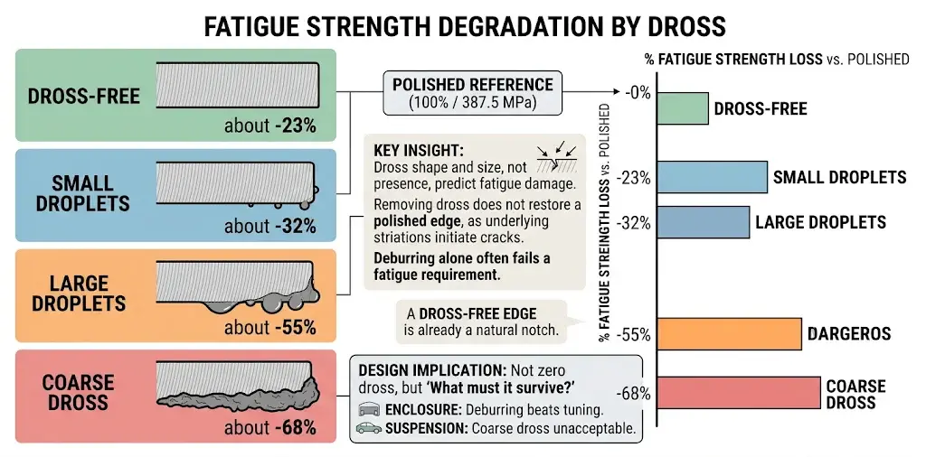
- Dross is a fatigue feature, not just a finish feature. On AISI 304, very coarse dross cut fatigue strength by 68% against a polished edge.
Diagnose laser cut exit defects by their shapes before tuning parameters
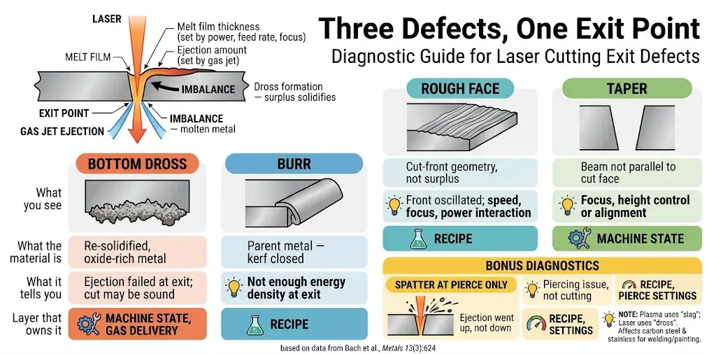
The melt film on the cut front has a thickness set by power, feed rate and focus; how much leaves the kerf is set by the gas jet. When the first outruns the second, the surplus solidifies on the lower edge — one imbalance, three shapes (Bach et al., Metals 13(3):624). Which shape you get is the diagnostic; read it before opening the parameter page.
| What you see | What the material is | What it tells you | Layer that owns it |
|---|---|---|---|
| Bottom dross: brittle, granular, flicks off | Re-solidified, oxide-rich metal left on the exit edge | Ejection failed at the exit; the cut may be sound | Machine state, gas delivery |
| Burr: ductile, continuous, folds over, needs a grinder | Parent metal — the kerf closed before the bottom separated | Not enough energy density at the exit | Recipe |
| Rough face: striations, chatter, nothing attached | Cut-front geometry, not surplus material | The front oscillated; speed, focus, power interact badly | Recipe |
| Taper: top kerf wider than bottom | Beam not parallel to the cut face | Focus, height control or alignment | Machine state |
| Spatter at the pierce only, clean elsewhere | Ejection went up, not down | Piercing, not cutting | Recipe, pierce settings |
Two notes. Plasma shops call the crust “slag”; on a laser it is dross. It bites hardest on carbon steel and stainless, where parts move on to welding, painting or assembly.
Dross shape and size degrade laser cut fatigue strength up to 68%
Most shops cost dross as finishing labour: a grinder, a few seconds per part. For parts that never see load cycles that is the whole cost — skip ahead. For parts that do, the numbers change the conversation.
A 2023 study cut AISI 304 at 2 mm, pre-deformed it by 28% and fatigued it at R = 0.1. The polished reference reached 387.5 MPa. The same material, cut and left as cut:
| Edge condition | Fatigue strength against the polished reference |
|---|---|
| Dross-free laser edge | about 23% lower |
| Small droplets | about 32% lower |
| Large droplets | about 55% lower |
| Very coarse dross (about 125 MPa) | about 68% lower |
Read the first and last rows together: even a dross-free edge sits about 23% below polished — a cut edge is a notch by nature. Removing the dross does not restore it — the striation relief underneath becomes the dominant crack initiation site, which is why deburring alone so often fails a fatigue requirement.
The transferable point: dross volume and shape, not its presence, predict the damage. A fine bead on a painted bracket is a finishing cost; a coarse, fused bead on a loaded part is a design risk. So the question is not “how do I get zero dross” but “what does this edge have to survive” — on an enclosure a deburring pass beats an afternoon of parameter hunting; on a suspension component coarse dross is unacceptable however it is finished.
Specify measurable edge radius and surface condition, not just zero burr
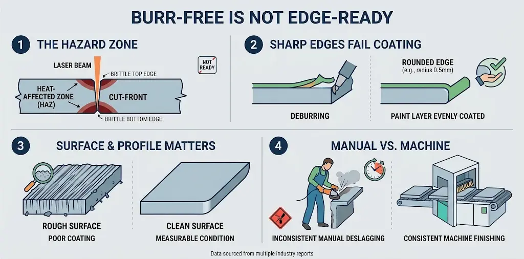
The instinct after a bad batch is to chase zero burr. Wrong target: cutting leaves a heat-affected zone that cools hard and brittle at the top and bottom corners. A blank can look burr-free and still fail downstream: deburring removes a sharp burr without creating a rounded edge, and coating does not adhere to a sharp edge (Brett Mandes, Canadian Metalworking, 23 October 2025). The face matters as much as the corner: deep striations and sharp profiles cause premature coating loss (TWI, EDGETECT2).
So write the requirement as two measurable things, a radius and a surface condition. “No burr” cannot be inspected, quoted or argued about at goods-in; “edge radius 0.5 mm, face free of attached dross” can. Written that way, the parameter chase has a stopping point — and the cheapest route is often a deburring or edge-rounding step, making the decision economic rather than technical.
Manual deslagging is inconsistent by nature: one shop installed a finishing machine to clean slag from its 15 kW lasers partly because hand work with grinders “always seems to be the case” (Dan Davis, The FABRICATOR, 20 October 2025). If the last operation is a person with a grinder, every edge depends on that person’s afternoon. Freshly cut blanks are a laceration hazard: US OSHA requires hand protection where hands are exposed to severe cuts (29 CFR 1910.138).
Track what the defect follows to instantly pinpoint the root cause
Everything above says what you have; this says who owns it, faster than any parameter test.
| Pattern | What it follows | Owner | First move |
|---|---|---|---|
| Every part, every job, gradual onset | Machine state | Consumables and optics | Window, nozzle, height response, gas under flow |
| Sudden, across a whole nest | One change: gas cylinder, nozzle swap, maintenance | Machine state | Ask what changed in the last hour |
| One material lot or heat number | The sheet | Material | Compare with the last known-good lot |
| One side of the sheet, one travel direction | Position or motion | Machine state | Re-cut the same part at another nest position |
| Corners and small features only | Dynamics | Recipe and geometry | Cut a coupon with corners, not a straight line |
| Pierce only, first 10 mm of a contour | Piercing | Recipe | Pierce parameters, not cutting ones |
| Top clean, bottom bad on one side of thick plate | Through-thickness delivery | Machine state, then recipe | Focus, then gas |
| Falls through the shift, recovers after a break | Thermal drift | Machine state | Cooling and warm-up behaviour, not the program |
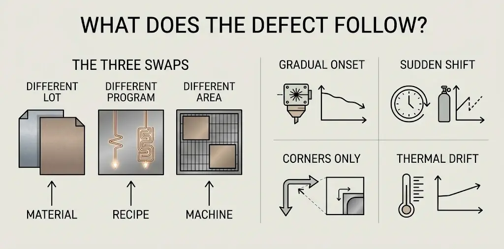
The three swaps are mechanical. Same part, different lot: if the defect follows the sheet, it is material. Same sheet, different program: recipe. Same part, different area: machine or sheet support. None needs a decision about which parameter to change — which is why they end arguments.
The clock is cheaper still. Almost every sudden, sheet-wide change has a human event behind it: a window changed at lunch, a cylinder swapped at shift start, a head serviced last week. It is the discipline behind our press brake troubleshooting guide: the signature narrows the search before anyone adjusts anything.
Check hardware, gas, and focus before changing cutting parameters
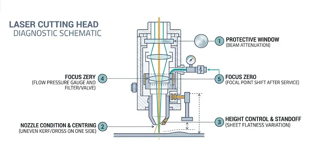
Consumables and gas change without anyone touching the program, so a program-based search never finds them. Each has a tell.
- Protective window. Degrades gradually, hits every material and thick plate first, reads as “the machine lost power”.
- Nozzle condition and centring. Direction-dependent dross: one side of a contour clean, the other not, worse on curves than straights. Check spatter, orifice deformation and centring before changing any parameter.
- Height control and standoff. Roughness that tracks the flatness of the sheet and worsens towards the middle of a nest.
- Gas delivery. Arrives suddenly, usually across a whole nest. A gauge read with the gas static proves nothing: read pressure under flow at the nozzle, and check for a partly closed valve, a loaded filter or a cylinder changed without purging.
- Focus zero after head service. Everything degrades at once and the taper changes; offsets from before the service are invalid.
One hard stop list belongs with every operator: never open optical assemblies beyond the documented cleaning procedure, never touch the source, never defeat an interlock, never run through a cooling alarm. Beyond those boundaries it is a service decision; improvising turns a defect into a repair.
Traceable part numbers make the comparison possible, which is why our spare parts and consumables are listed by nozzle, window and ceramic type rather than by machine.
Read dross shape, adjust one parameter at a time, and stop when met
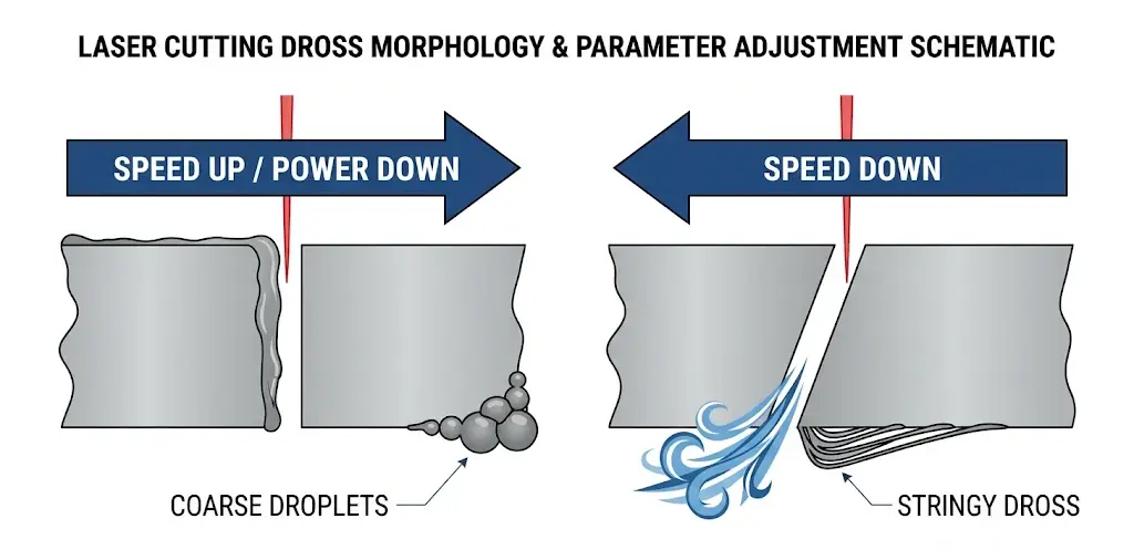
Most published advice is “slow down” — right about half the time, and the morphology tells you which half. Too much energy per millimetre and the melt film thickens: coarse droplets, worse the more you slow down. Speed too high and the cut front leans, the jet turns turbulent, and removal turns irregular: stringy, direction-dependent dross on an inclined front. Both are dross, corrected in opposite directions (Bach et al., Metals 13(3):624). Read the shape before you touch the feed.
Once section 4 has pointed at the recipe:
- Fix the state first. A recipe tuned around a worn window is a recipe for one afternoon.
- Confirm the recipe matches the job — grade, measured thickness, gas, nozzle, cutting height. Half of that record missing is itself the finding.
- Take the direction from the morphology, not from habit. Coarse droplets mean too much energy per millimetre, so raise speed or reduce power; stringy dross on an inclined front means speed is already too high.
- Change one variable and cut a coupon from the same sheet — a plate through the machine has a different thermal history. Two changes between coupons is an anecdote.
- Stop when the edge meets the written requirement, not when it looks perfect.
The four variables have their own setting logic; the recording discipline is set out in Fiber Laser Cutting Parameters: Speed, Power, Focus and Gas. Gas selection belongs to Laser Cutting Assist Gas: Oxygen vs Nitrogen vs Compressed Air; dross types by gas and material are catalogued in Laser Cutting Dross and Burrs: Causes and Troubleshooting.
Training is the unglamorous lever: an operator who can name the dross shape and predict the fix beats any cut chart, because that chart was written for someone else’s material. Operator training on defect recognition and trial cuts is where that judgement is built.
Some defects stem from material and design, not machine parameter

Some defects cannot be tuned out; recognising that early is worth more than another coupon.
Surface condition. Mill scale, oil, rust and coatings change how the surface absorbs the beam and where the standoff really sits; hot-rolled plate is not the same job as pickled and oiled.
Flatness and internal stress. Laser cutting adds thermal stress of its own; a sheet that is not flat changes the standoff across the nest, and a tip-up is a cutting event rather than an accident (Dan Davis, The FABRICATOR). If roughness follows the sheet rather than the part, look at the sheet first.
Lot-to-lot variation. Chemistry and hardness shift edge behaviour enough that the same program gives a different bead on the next delivery. Keep the lot number on the route card, so the next bad batch can be compared with something other than memory.
The drawing. Hole diameter against thickness, inside corner radius, narrow webs and common-line edges set a floor under achievable edge quality. Below a certain hole size the cut never reaches steady state, and a shared edge can only be compensated for one of its two parts — no parameter search finds those. Striations and taper, the two face-level symptoms, are treated separately in Why Does Laser Cutting Produce Rough or Uneven Edges?
Five moves that usually make it worse
| Move | Why it backfires | What to do instead |
|---|---|---|
| Turn up the power | Adds melt without adding ejection when the limit is gas, focus or a tired window | Confirm state, then take direction from the dross shape |
| Slow the whole job down | Can convert a fast-cut defect into a coarse-dross defect, with more heat in the part | Slow only once the morphology says the front is leaning |
| Raise gas pressure | Past the nozzle's design point you get shock and turbulence rather than shear | Check nozzle, centring and pressure under flow |
| Edit the kerf offset | An offset moves a contour by half a kerf; it cannot change a face or an attachment | Separate the dimensional error from the edge defect first |
| Nudge focus with no zero reference | Destroys the only datum the next shift needs to reproduce anything | Re-establish the zero, then move in known increments |
Escalate persistent defects with four key records for remote diagnosis
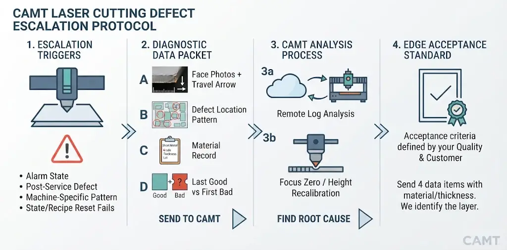
Stop and escalate when the defect comes with an alarm, follows a head service, tracks the machine rather than the part, or survives a full reset of state and recipe. Send four things; the diagnosis usually takes one exchange instead of a week:
- Photographs of both faces, with a scale and an arrow for the direction of travel.
- The location pattern: whole nest, one side, small features, pierce only, first part of the shift.
- The material record: grade, measured thickness, heat or lot number, surface condition.
- The last good sample, and what changed between it and the first bad one.
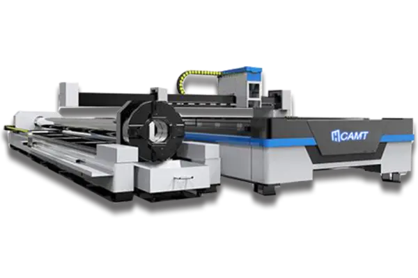
At CAMT we build machines that must answer this question, so it is fair to say what configuration changes the exposure. The fiber laser cutting machine range covers three architectures: the enclosed ULE with twin exchange tables for continuous production, where a mid-nest defect must be caught before the next pallet, and the open-type ULF single-table machine for mixed work where the operator watches the cut. Configuration descriptions, not edge-quality guarantees.
Remote diagnostics reconstruct a persistent defect from logs, consumable history and parameter versions before anyone travels; planned service and calibration is where focus zero and height response are re-established after a head change; the service scope sets out coverage and intervals.
We will not claim a machine eliminates dross, publish a universal parameter set, or assert compliance with an edge-quality standard on your behalf. Edge acceptance is set on your parts, against a criterion your quality function writes and your customer signs. Send the four items above with your material and thickness and we will say which layer the evidence points at.