Excessive burrs and dross are common problems when laser cutting aluminum, especially when processing medium- and thick-thickness sheets. Even when a fiber laser cutter has sufficient power, poor focus positioning, unstable nitrogen pressure, incorrect cutting speed, or improper nozzle alignment can leave solidified aluminum attached to the bottom edge of the workpiece. These defects increase deburring time, create inconsistent edge quality, and raise the overall cost per finished part. To laser cut aluminum with minimal burrs and dross, you need to balance laser power, cutting speed, focal position, nozzle condition, and assist gas flow. This guide explains how to identify the causes of aluminum cutting defects and systematically optimize your cutting process for cleaner, more consistent results
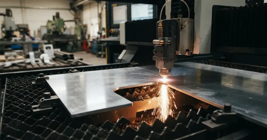
Diagnose laser dross shapes first, then run single-variable cut tests
Different dross shapes have different causes; diagnosing from the bottom edge saves hours of blind knob-turning:
- Uniform icicle dross along the whole edge — the melt is consistently leaving too late: gas pressure below what the thickness needs, or power and speed out of balance.
- One-sided dross — the jet is not centered or intact. A dented, spattered, or misaligned nozzle biases the flow to one side.
- A hard, glassy bead that tools struggle to remove — the melt re-froze slowly — excess heat input: speed too low for the power, or focus in the wrong zone.
- Powdery residue that brushes off — often acceptable on non-cosmetic parts; check whether the application truly requires a zero-dross edge before spending gas and time on it.
- Dross plus an incomplete cut in the same spot — the kerf is losing the beam before the bottom — a penetration problem, which changes the fix.
Speed behaves counterintuitively on aluminum: the 2019 study showed that pushing speed too low raises dross — a larger molten pool gives the gas more melt than the jet can clear. Rather than guessing, run a controlled test that changes one thing at a time:

| Test | Laser power | Cutting speed | What it tells you |
|---|---|---|---|
| A | Current | Current | Baseline — keep the coupon for comparison |
| B | Unchanged | 5–10% lower | Whether energy input is short (thin sharp burrs ease) |
| C | Unchanged | 5–10% higher | Whether heat input is excessive (bead softens, kerf narrows) |
| D | Trimmed to suit | Best speed from B/C | Final balance — re-cut the same corner to confirm |
Cut a fresh coupon for every step. The winning setting achieves complete penetration, acceptable edge quality, and stable production — not necessarily the fastest speed.
The general low-speed versus high-speed dross theory applies to every material, so the troubleshooting pillar covers it in depth across materials. Fiber Laser Cutting Troubleshooting: Dross, Burrs and Rough Edges
Verify aluminum alloy grades, clean surfaces, and keep sheets flat

“Aluminum” is not one material. Wrought aluminum alloys are registered by the Aluminum Association under a four-digit designation system tied to chemical composition limits (the Teal Sheets, revised December 2025), and the first digit tells you the alloying family — 1xxx commercially pure, 5xxx aluminum-magnesium, 6xxx aluminum-magnesium-silicon, 7xxx aluminum-zinc. Those additions change absorption, melt viscosity, and solidification — the same program cuts two alloys differently.
- Establish parameters per alloy, not per “aluminum.” Pure 1xxx reflects more and flows more freely; high-strength 2xxx/7xxx plate solidifies differently again.
- Record what the mill cert says, not what the paint stencil says. Mixed or mislabeled stock shows up in the shop as dross nobody can explain.
- Watch the surface. Oil, drawing compound, heavy oxide, and water staining all disturb how the beam starts the cut and how the melt wets the kerf — a wiped, dry sheet cuts more predictably.
- Keep the sheet flat and supported. A warped sheet changes nozzle distance mid-cut, and aluminum is less forgiving of standoff variation than steel.
If incoming material varies batch to batch, no parameter fix will make cut quality stable — the variation is in the metal before the machine ever fires.
Assist Gas: Nitrogen First, With Eyes Open
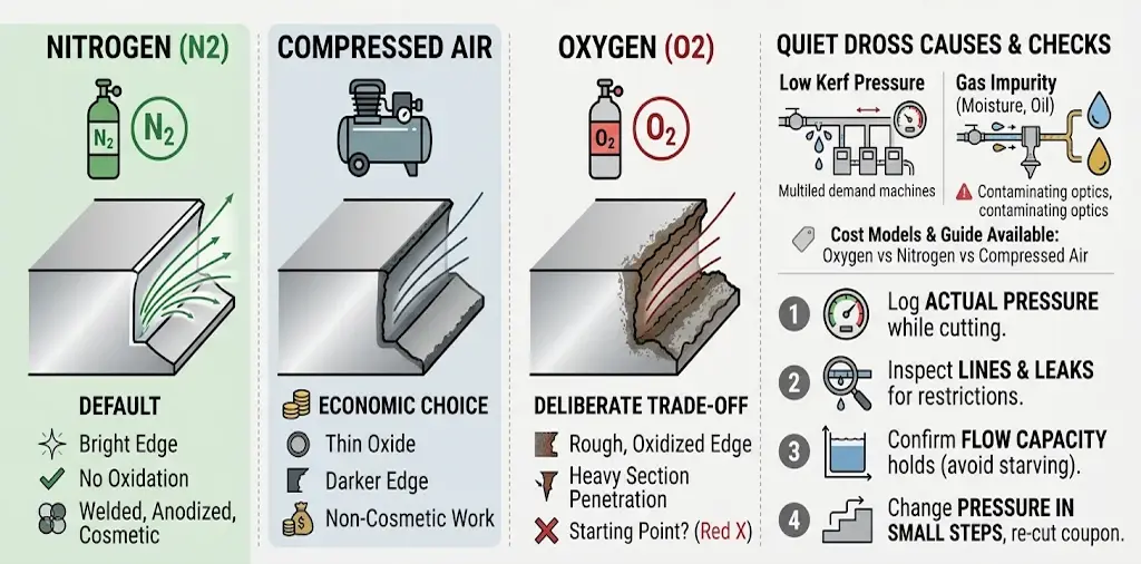
On aluminum, the assist gas does more mechanical work than on steel: it has to shear a clingy, fast-refreezing melt out of the kerf.
- Nitrogen cuts as a neutral, inert jet: no oxidation, a bright edge, the strongest ejection at pressure. Default where the edge will be welded, anodized, or seen.
- Compressed air carries oxygen, so it leaves a thin oxide and a darker edge, but it is a legitimate economic choice on non-cosmetic work.
- Oxygen adds reaction heat that helps thick sections penetrate but tends to leave a rougher, oxidized edge with more residue on aluminum — a deliberate trade-off, not a starting point.
For a sense of scale on medium-thick plate: the 2019 experiment reached minimum dross height on 8 mm alloy at 5.4 kW with 1100–1500 kPa. Those numbers belong to that alloy, thickness, and rig — evidence that power and pressure must rise together, not settings to copy.
Two gas-side details quietly cause aluminum dross. Pressure at the kerf, not at the gauge: long or undersized lines, leaks, and shared demand from other machines drop what actually arrives at the nozzle. Purity and dryness: moisture or oil in the gas line ends up in the kerf and on the optics. When pressure looks right but dross persists, walk four checks in order:
- Log the actual pressure while cutting, not the idle regulator reading.
- Inspect lines, valves, filters, and fittings for restrictions or leaks.
- Confirm the supply holds flow capacity at full demand — a generator or manifold serving other machines may starve mid-cut.
- Change pressure in small steps, re-cutting the same coupon corner each time.
Gas cost per meter of cut, and when air or oxygen pays, is covered with a cost model in the assist gas guide. Laser Cutting Assist Gas: Oxygen vs Nitrogen vs Compressed Air
Ensure melt has a clean exit to avoid bottom dross

Everything at the bottom edge depends on whether the melt has a clean exit. Three hardware factors decide that.
Focus position. Recent work on 1.6 mm 2024-T3 sheet with a 6 kW-class fiber source tested 40 parameter combinations and found the best combination of dross height, roughness, and heat-affected zone at a focus below the sheet surface, with the positive-defocus sample showing measurably worse results (Chen et al., Chinese Journal of Lasers, 2026). The logic: focusing into the lower part of the section keeps energy at the bottom of the kerf where the melt has to leave. The depth belongs to that alloy, thickness, and optics — start from your machine’s library recipe and tune on coupons. Focus sign conventions also differ between controllers, so check your own manual before translating any advice.
Nozzle condition and centering. A spattered or dented nozzle skews the jet, and skewed jets produce one-sided dross that no parameter change will fix. Inspect the nozzle first — the cheapest check on the list — and keep spare nozzles and protective lenses on hand; replacements are stocked on the spare parts and consumables page.
Kerf width and the skeleton. On thicker sections, a wider kerf gives the melt more room to leave and makes parts easier to separate. As MMS reported from Trumpf’s product engineering, larger beam diameters that produce wider kerfs are required to cut thick material with better process stability and more reliable part removal (Korn, Modern Machine Shop). If parts tear dross at breakout on thick aluminum, the beam geometry — not just the gas — may be the constraint.
Piercing. The pierce is the most violent moment of an aluminum cut: molten metal splashes toward the optics, and a bad pierce leaves a poor entry for the contour. Follow your machine’s aluminum piercing strategy — controlled power, adequate pierce height, pierce points in scrap — and treat any change in piercing behavior as an early warning about the nozzle and lens.
Aluminum Dross and Burr Diagnosis Table
The table separates material-side from process-side causes so you can walk it in order. It assumes nitrogen cutting unless noted.
| Symptom at the edge | Most likely cause | Check first | Next move |
|---|---|---|---|
| Uniform icicle dross, full length of cut | Gas pressure short of the thickness' need, or power/speed imbalance | Gauge pressure vs. recipe; line losses and leaks | Raise gas and re-cut; then adjust speed in small steps |
| One-sided dross | Nozzle damaged, spattered, or off-center | Nozzle bore and concentricity | Replace or re-center the nozzle before touching parameters |
| Hard glassy bead, hard to remove | Excess heat input — melt re-freezes slowly | Speed vs. power balance; focus position | Raise speed toward the recipe window; verify focus |
| Dross plus uncut bottom in places | Insufficient penetration | Power, focus, pierce quality | Stop cleaning up — fix penetration first |
| Dross only near pierces and corners | Heat concentration at dwell points | Pierce strategy; corner slowdown settings | Adjust pierce parameters; review corner logic |
| Quality drifts across the sheet | Sheet flatness, standoff variation, or alloy change mid-job | Sheet support; mill cert vs. stencil | Re-level material; verify alloy per bundle |
| Clean on 5052, drossy on 6061 (or vice versa) | Parameters tuned to one alloy | Parameter library entries per alloy | Establish and save per-alloy recipes on coupons |
| Sudden protective-lens failures while cutting aluminum | Back-reflection or spatter load beyond the optics' rating | Lens condition; machine's reflective-material rating | Stop and confirm configuration with the supplier (next section) |
When the Problem Is the Configuration, Not the Settings

Some aluminum problems cannot be tuned away because they were designed in — or designed out. Solid and molten aluminum both reflect a large share of near-infrared laser light, and reflections that travel back up the beam path can damage the source and optics. Modern sources and cutting heads include back-reflection protection for this, and machine makers rate their equipment for reflective materials to different degrees — the same MMS report notes a conventional 5 kW fiber machine was typically limited to around 0.75-inch aluminum, a vendor’s figure that illustrates how much the ceiling depends on configuration rather than wattage alone.
If you are buying, or have inherited a machine, settle these in writing with the supplier before production:
- Is the source and cutting head rated for the aluminum alloys and thicknesses you will run, including piercing duty?
- What back-reflection protection does the configuration include, and what alarms or derating does it apply?
- What optics and nozzle grades does the maker recommend for aluminum work, and at what inspection interval?
We do not assert suitability for any specific machine and material combination — that confirmation has to come from the supplier in writing, because protection schemes differ between brands and power classes. If quality deteriorates unexpectedly on a machine already in service, CAMT’s technical support service can help separate equipment causes from process causes.
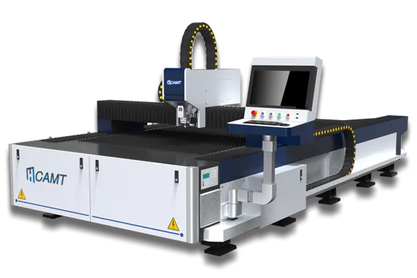
CAMT builds fiber laser machines for different duties: the fiber laser cutting machine range covers open-type and fully enclosed exchange-table designs. The ULF open-type fiber laser cutting machine suits shops that want full sheet access and fast loading, while the ULE enclosed exchange-table fiber laser cutter pairs an enclosed cutting zone with a table that swaps finished sheets for fresh stock — useful when edge quality depends on stable, repeatable conditions. For a specific alloy and thickness, ask us to run a cutting trial so the parameters are proven on your material, not estimated from a chart.
The same logic extends to other reflective metals: copper and brass behave differently again, with their own absorption and melt behavior. How to Laser Cut Copper and Brass Safely and Effectively
Keep Dross Out of the Bins, Not Off the Parts
Removing aluminum dross is worse than preventing it: the residue contains hard aluminum oxide particles that chew through deburring media, and icicle dross adds hand work to every batch. Three habits keep the bins clean.
Cut a coupon before the batch. Take a corner of the actual sheet, cut the worst features — long straights, small holes, tight corners — and inspect the bottom edge before committing the nest. Ten minutes of coupon beats a pallet of rework.
Log the recipe that passed. A parameter library turns one operator’s luck into the shop’s knowledge:
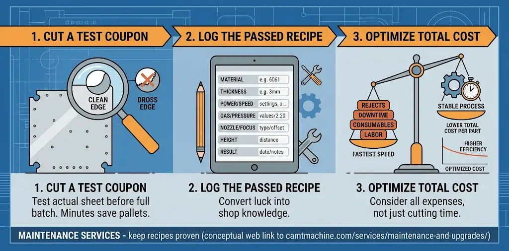
| Field | What to record |
|---|---|
| Material and thickness | Actual alloy (e.g. 5052, 6061) and measured sheet thickness |
| Power and speed | Settings that passed the coupon test |
| Gas and pressure | Gas type and working pressure at the machine |
| Nozzle and focus | Nozzle type and diameter; verified focus offset |
| Cutting height | Nozzle-to-sheet distance |
| Edge result | Burr, dross, striations, taper; date and operator |
Mind the total cost per part. The fastest speed is not always the most economical: gas, electricity, consumables, deburring labor, and rejected parts land in the same account. A slightly slower but more stable process often delivers a lower total cost per part, and consumables replaced before they fail cost less than the downtime they cause. For the longer term — calibration, optics, motion health — CAMT’s maintenance and upgrade services keep a proven recipe proven.