When your fiber laser cutting machine is not cutting through the material completely, the problem is not necessarily insufficient laser power. You may notice that the laser melts the top surface but leaves the bottom attached, produces intermittent uncut sections, or suddenly fails to cut material that previously processed without problems. These issues can result from incorrect cutting speed, improper focal position, insufficient assist gas pressure, contaminated protective lenses, damaged nozzles, or unstable laser output. Identifying the actual cause before changing machine settings is essential to restoring cutting performance, preventing material waste, and avoiding unnecessary downtime.

How to Diagnose Incomplete Fiber Laser Cuts at the Bottom of the Kerf
The beam converges to a waist and then diverges, so below the waist the spot grows and intensity falls. The jet leaves the nozzle at full momentum, expands, picks up metal vapour and has to clear a channel deeper than it was designed for. Heat and momentum are richest at the top surface and poorest at the exit, which is why every through-cut is decided at the bottom, at whichever reserve is thinnest there.

| What you see | What is short | The measurement that settles it |
|---|---|---|
| Pierces, then dies within the first few centimetres | Gas momentum | Pressure at the head with the jet running; orifice against thickness |
| Holds on a short contour, fades on a long straight | Gas supply or thermal drift | Log head pressure and chiller temperature through one full pass |
| Fails at corners, small holes and tight radii only | Program dynamics | Programmed feed versus the speed the controller actually reached |
| Clean at one end of the table, weak at the other | Standoff and height control | Nozzle standoff at both ends, height control off |
| Fine on thin sheet, fails on thick | Depth of focus | Section a coupon; compare entry and exit kerf width |
| One side of a contour clean, the other fused | Centring | Nozzle centring on a target, then repeat with a new nozzle |
| Everything degraded since a window or head service | Optics, or focus zero | Burn spot on the window; re-check focus zero |
| Fails only while a second machine is cutting | Plant gas capacity | Pressure at both heads while both are cutting |
Every row can be settled in minutes with what is on the floor, and “it worked yesterday” is data: a decline over weeks is consumables, a step change overnight is an event. The wider defect map is in Fiber Laser Cutting Troubleshooting: Dross, Burrs and Rough Edges.
Troubleshooting Fiber Laser Beam Energy Loss and Incomplete Cuts

The source is the last thing to suspect and the first thing people blame. A fiber source that has genuinely lost output is rare, and proving it takes a measurement at the workpiece, not a bigger number in the program. Turning power up instead widens the entry, feeds a melt the jet cannot clear, and makes the bottom worse.
Work forwards from the source, in the order the beam travels:
- Speed against thickness, not against the last job. Speed sets how much energy lands per millimetre of cut. Too fast leaves the beam no time to melt through; too slow overheats, widens the kerf and puts dross back on thin sheet. If shaving the feed rate fixes penetration, the recipe was wrong for that thickness, not the machine.
- Window and lens. A contaminated window absorbs, heats and can take the optics with it, so a haze ring, burn spot or spatter crater is a finding, not a maintenance item to schedule later. Consumables listed by nozzle, window and ceramic type make the swap traceable.
- Focus zero after head work. A lens seated a fraction off its seat moves the waist, and every offset recorded before the service is now wrong. The machine keeps cutting — badly — on settings that used to work.
- Program power versus delivered power. A reduced level inherited from the last job, an edge-quality mode or a ramp left active on the layer costs nothing to rule out.
- Thermal drift. A drifting chiller, or a head heat-soaked after two hours of thick plate, moves focus with no parameter changing. If the failure arrives at the same point in the shift, measure temperature first.
Two boundaries before touching optics: isolate the beam before any window or lens inspection, and leave the source and fiber delivery closed unless the manufacturer authorises the work — the hazard is invisible and reflected as well as direct.
If the failure appears on one lot or heat number only, stop diagnosing the machine. Rust, mill scale, oil and coating change how much beam enters the metal — a loose scale jacket is worse than a heavy one, because the beam cuts two surfaces with an air gap between them — and nominal thickness is often not actual thickness. Measure the sheet, then repeat the same program on a known-good offcut.
Ensuring Assist Gas Clears Molten Metal for Complete Laser Cuts
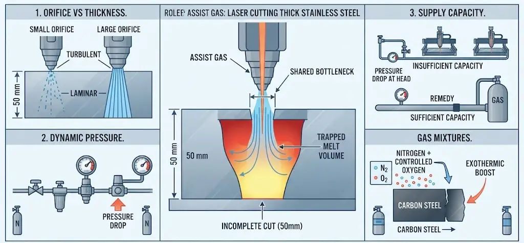
Melting is not cutting. The cut advances only if the melt leaves, and the jet’s ability depends on orifice, pressure, standoff and how much melt it carries — all of which can read correctly at the gauge and be wrong at the kerf.
The clearest evidence is an experiment where power was the only variable: 50 mm austenitic stainless, nitrogen at 10 bar, 7 to 13 kW. Front-surface kerf width barely changed while the melt volume inside the material rose, so more power demanded a gas mass flux the unchanged entry could not supply, and melt discharge was hampered — Kim et al., Applied Sciences 12(1):495; at the top of the speed range the material was not completely cut. One experiment’s conditions, not a setpoint, but the direction generalises: power and gas are not independent, and the kerf entry is their shared bottleneck.
Three checks, in order:
- Orifice against thickness. Thick sections want a larger orifice and a longer, calmer jet. An undersized orifice turned up to high pressure gives a fast, turbulent jet that disperses before it reaches the bottom.
- Pressure where the work is. A gauge read with the gas static proves nothing. Read it under flow at the head, then look for a partly closed valve, a loaded filter or a line never sized for this machine. Purity belongs here too: off-spec nitrogen will not clear a deep kerf however much pressure you add.
- Supply capacity, not supply pressure. Pressure holds until demand rises. Two machines will find the limit of a plant plumbed for one, and the remedy is pipe capacity and storage, not a higher setpoint at the regulator.
Oxygen brings exothermic energy on carbon steel; nitrogen brings momentum only. Thick-plate work increasingly runs mixes — enough nitrogen to flush the kerf, a controlled dose of oxygen for the reactive boost — as Tecoi USA’s Carlos Rodriguez described to The FABRICATOR. Changing gas re-qualifies the process; the economics belong to Laser Cutting Assist Gas: Oxygen vs Nitrogen vs Compressed Air.
There is a ceiling as well as a floor: past a point, more gas disturbs the cut front instead of clearing it, so “raise the pressure” is not a universal fix. The shape of that limit is in Laser Cutting Dross and Burrs: Causes and Troubleshooting.
Geometry: focus, focal length and where the waist really sits

Focus position is the parameter most often changed and least often verified, and where the controller’s sign convention can send you the wrong way: on some controls a positive value puts the waist below the surface, on others above. Check the manual, then confirm zero with a test cut.
Focal length precedes it, and it is a straight trade:
- Short focal length: small spot, high intensity, short depth of focus. Excellent on thin sheet, hopeless on thick plate, because the beam has diverged well before the bottom.
- Long focal length: larger spot, much deeper usable waist. For a given beam diameter entering the lens, doubling the focal length roughly doubles the spot and quadruples the depth of focus, so intensity falls to about a quarter — less intensity, but still present at depth.
A machine that cuts 6 mm beautifully and refuses 12 mm is therefore not necessarily underpowered: it may have the wrong lens, or a focus position that puts the waist where the cut starts rather than where it ends.
Two facts settle it without instruments. Entry and exit kerf width map the beam’s path through the thickness: exit narrower than entry means the waist sits above the bottom, exit wider means below. Section one coupon and you know what the controller has been doing, whatever the display says. And standoff must stay constant for any of this to hold, which is why plate flatness, slat condition and height-control calibration are cutting parameters in disguise — a plate bowing between the slats changes focus for that part of the nest.
Centring is the third leg. An off-centre nozzle throws the jet asymmetrically, so the melt on one side of the kerf has momentum behind it and the other side does not. Check it on a target, then repeat with a new nozzle to separate a worn orifice from a misaligned head.
And if there is no hole at all — spatter blowing upward, a molten mound rather than a crater — that is a piercing problem, not a cutting one, with its own parameters. Chase it there before cutting settings are touched.
Prove it is through before the part leaves the table

The most expensive version of this fault is the one that ships: a part held by a thin bridge at the bottom looks cut, measures close to nominal, and fails at the welder. Partially cut parts also tip up into the head and take out the nozzle or the window, and a nest 80% cut cannot be re-nested around the failure. Re-running the contour slower is a bad trade: it adds heat to a section already overheated once.
- Watch the exit plume, not the top. A consistent conical plume of sparks leaving the underside means the beam is cutting the full section. A plume that sprays sideways or trails the head is a cut losing heat; sparks bouncing on the leading edge usually mean it is not melting through — and once that starts, material can blow back up the kerf and the laser can begin to weld the cut closed, as The FABRICATOR’s plate-surface analysis describes.
- Lift, don’t lever. With tabs intact, lift the part gently at two corners. A cut part rocks free or holds on its tabs; a partially cut one bends at the bridge. Never use a bar to prove a cut, and never reach into the work envelope while the program can restart — stop the program, isolate the energy, then look.
- Cut a proof coupon, not a memory. One short contour on an offcut from the same sheet, same recipe, exit side inspected. Ninety seconds of proof beats an hour of adjusting on the nest.
When gas supply is the suspect, one test separates supply from setting: a long zigzag up and down a sheet without lifting the head, several minutes, two or three thicknesses, with head temperature watched alongside. If it cuts well and then suddenly goes bad, the constraint is gas flow, not the recipe.
What to write down
Record what you proved: without it, the next shift repeats the diagnosis. Building one is set out in Fiber Laser Cutting Parameters: Speed, Power, Focus and Gas.
| Test item | What to record |
|---|---|
| Material | Grade, heat or lot number, surface condition |
| Thickness | Measured, not nominal |
| Power | Commanded value, and any mode or ramp in effect |
| Speed | Programmed feed, and what the controller actually reached |
| Gas | Type, purity, pressure at the head under flow |
| Focus | Value, and which sign convention the control uses |
| Nozzle | Orifice, condition, centring result |
| Result | Exit-side condition: through, bridged, dross, edge quality |
Specifying Machine Configuration Parameters to Prevent Cutting Failures

Is it a fault, or is the machine short of capability? If it never cut this thickness, no adjustment will fix it. Reduce the requirement to one number — the thickness you must cut next year, in the material you cut most — then check beam quality, head focusing capability, gas supply capacity and structure against it, not the wattage on the badge.
Four things belong on the order, not in a service call later:
- Gas supply sized for the machine, not the building. Required flow at the head, how many machines may cut at once, and who verifies it.
- A nozzle range, not a nozzle. Ask which orifice range the head supports, the consumable part numbers, and how centring is checked.
- The focal length for the thickness range you actually run.
- Height control and table condition, because consistent standoff is a machine property, not an operator skill.
The nozzle, the beam shaping and the control system are one process, not three purchases: Fraunhofer ILT develops cutting nozzles, optics and control together, and runs thick-sheet cutting as a research field of its own.
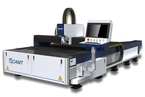
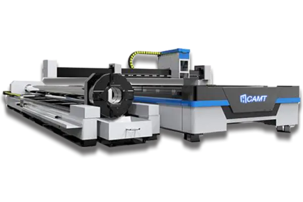
We do not assert suitability or an achievable thickness for your material and drawing; that confirmation has to come from the equipment supplier in writing, against the configuration you bought. What we publish is the range: ULF open-type machines at 1–6 kW, ULE enclosed exchange-table machines at 6–12 kW, and up to 12 kW+ across the range on the fiber laser cutting machine overview.
Send the numbers, not the description
Send the material, the measured thickness, gas and pressure at the head, nozzle orifice and focus value, and technical support can work from your log and the exit-side result rather than a phone description — or quote around the range you actually cut rather than the sample.