Aluminum cracks on a press brake for one reason: the outside surface of the bend is stretched past the ductility that the specific alloy and temper bring to that bend. Every fix works one side of that equation — lower the strain with a larger inside radius, a wider die and a cross-grain bend, or raise the ductility with a softer temper and clean, deburred edges. The hard part is that aluminum fails quietly. It forms at a fraction of steel’s force, so no tonnage alarm ever sounds, and the only guardrail is the setup you chose before the ram came down.
- Start with the temper, not the tooling. A 6061-T6 part and a 5052-H32 part of identical thickness obey different radius rules; no die selection rescues the wrong temper.
- Decide the inside radius first, then work backwards to V-die opening, punch nose and minimum flange.
- Use a wider die than you would for steel where the radius requires it; aluminum’s low forming force makes wide dies cheap insurance.
- Bend across the rolling grain, and deliver deburred edges into the bend zone — burrs and dross are ready-made crack starters on the tension side.
- Do not force the radius with bottoming or coining, do not reach for a torch, and finish the part after bending, not before.
If you already have cracked parts on the bench, our sheet metal cracking guide reads the crack’s location and direction as a diagnostic. This article stays on the aluminum side: picking the material condition, radius and tooling so the crack never starts.
Why Aluminum Cracks Where Steel Forgives
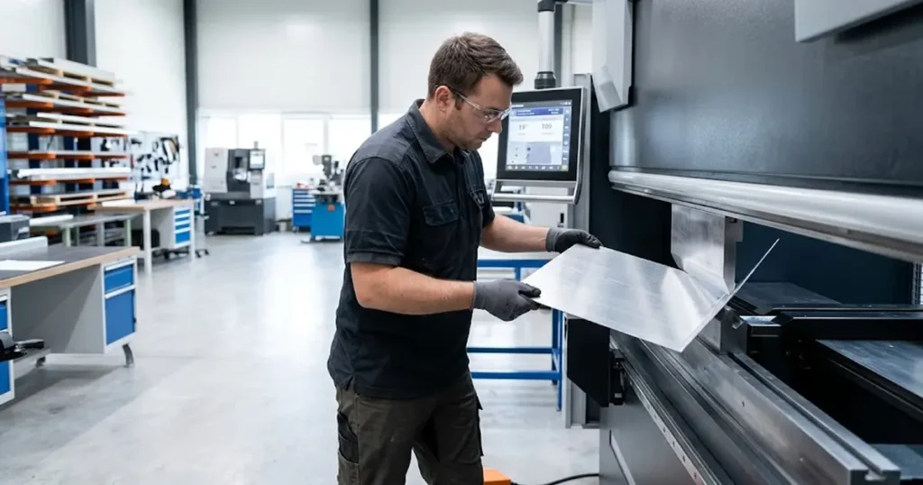
Elongation sets the limit, and it is where aluminum stops being one material: thin-sheet 5052-H32 around 12 percent, 6061-T6 lower in thin gauges, annealed O-tempers double or triple that — orientation numbers only, since the governing value is on the mill certificate for the lot you are bending, with ASTM B209 setting the guaranteed minimum elongation for each alloy, temper and thickness.
Aluminum also fails in a way steel rarely does: creasing. When the punch nose is far sharper than the radius the material wants to form, the bend line loses its integrity and the part is scrap, not a feature. That behavior shapes every tooling rule below.
Start With the Temper, Not the Machine
The fastest way to waste a shift is to treat the alloy as the decision. Within one alloy, the temper decides almost everything — and the standards agree: sheet and plate specifications require that each alloy, temper and thickness be capable of being bent cold through a specified angle around a pin without cracking. Bendability is a certified, per-condition property, not a family trait.
| Alloy & temper | Behavior at the brake | When the print demands a tighter bend, the first lever is |
|---|---|---|
| 5052-O | Very ductile; tolerates tight radii and aggressive forming | Almost nothing to fix — check edges and grain, proceed |
| 5052-H32 | The sheet-metal workhorse; good strength-to-formability balance | Radius one step larger, or drop a temper (H34→H32, H32→O) if strength allows |
| 3003-H14 | Soft and forgiving; common in HVAC and enclosures | Usually bends as-printed; verify grain direction on narrow flanges |
| 6061-T4 | Formable for a heat-treatable alloy; ages to useful strength later | Often bends as-printed; confirm aged properties with the supplier |
| 6061-T6 | Strong but stiff; the most common cracking complaint in fab shops | Larger radius first (often 2–4× thickness); then a T4 trade-off, or form in O and heat treat |
| 7075-T6 | High strength, little formability; not a bending alloy at tight radii | Treat as a design problem — radius, temper or process qualification with material-specific data |
6061-T6 dominates that list because it is everywhere — enclosures, brackets, parts designed by people who never intend to bend them. And cast aluminum never belongs in this conversation at all: as one forming specialist puts it, cast material does not form, it just breaks, so a “6061 bracket” that keeps snapping may not be wrought stock.
The Trap: Aluminum Never Warns You
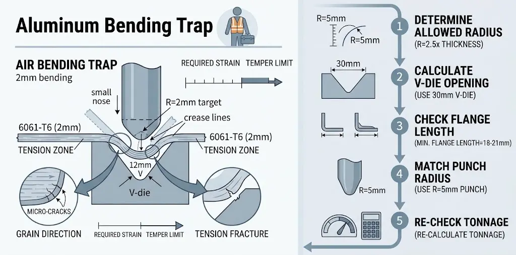
A shop takes a 2 mm 6061-T6 enclosure bracket with a 90° bend. For 2 mm mild steel the standard die in the rack is a 12 mm V — 6× thickness — so the operator reuses it. Air bending forms the inside radius at roughly 0.16–0.17 of the die opening, so the part comes out at about 2 mm, or 1× thickness. Comfortable for mild steel; for 6061-T6 it is roughly half of what the temper tolerates across the grain.
The machine says nothing. The aluminum section needs well under half the forming force of the equivalent steel bend, and a wider die cuts that further: no pump strain, no overload trip, no vibration. Every signal a press brake uses to say “this setup is wrong” stays silent, because from the machine’s point of view the job is trivially easy. The only evidence is hairline cracks, usually where the bend runs near the grain or a cut edge put a flaw in the tension zone.
The fix chain is the whole article in five lines:
- Decide the radius the temper accepts: say 2.5× thickness = 5 mm.
- Back out the die opening: at ~0.16×, a 5 mm radius needs roughly a 30 mm V — two and a half times wider than the steel die.
- Check the flange: the part must present at least the minimum supporting flange for a 30 mm die — 0.6–0.7 of the opening, so 18–21 mm here. A shorter flange needs different die geometry or a design change, not a narrower die.
- Match the punch nose to the 5 mm target, or the punch creases the line it is supposed to form.
- Re-check tonnage and crowning with the wider die — for aluminum, almost always a formality.
Skip that chain and no operator skill rescues the setup, because the constraint was never force — it was the strain budget of a T6 outer fiber.
Set an Inside Radius the Alloy Can Survive
Published minimum radii are starting ranges that assume cross-grain bends, deburred edges and room-temperature air bending. Your supplier’s bend-test data for the actual lot overrides every chart.
| Alloy & temper | Typical minimum inside radius, bend across grain | Practical notes |
|---|---|---|
| 5052-O | ~0.5–1× thickness | Can be formed nearly flat; the choice for tight work |
| 5052-H32 | ~1–1.5× thickness | Most common enclosure and tank sheet; forgiving |
| 3003-H14 | ~0.5–1× thickness | Soft; watch grain direction on narrow flanges |
| 6061-O | ~1× thickness | The form-and-heat-treat route starts here |
| 6061-T6 | ~2–4× thickness | The 4× end is safer; along the grain, expect to need more |
Read it as a floor, not a spec: with-grain bends, laser-cut edges, cold shops and bottoming all push the safe radius toward the larger end. Enlarging the radius also moves the flat pattern, bend allowance and flange dimensions — which is why the radius belongs in design review, not in a rescue attempted after the first batch cracks.
Choose the V-Die and Punch Nose
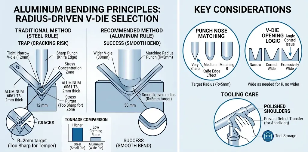
Because the air-bent radius follows the die opening, die selection for aluminum is really radius selection. The 6–8× thickness rule is a steel-era starting point; once a temper demands more radius than that opening produces, the opening has to grow — and aluminum’s low forming force means the wider die costs almost nothing in tonnage. General logic is in our V-die opening guide; the aluminum rules are these:
- Let the radius pick the die, not the thickness. The bracket above needed a 30 mm V because 6061-T6 asked for a 5 mm radius; a thickness-based rule would have kept the 12 mm die and kept the cracks.
- Match the punch nose radius to the target radius. A nose far sharper than the radius the material wants concentrates the whole stroke into a knife edge. Bottom-bending guidance makes the same point: use a punch tip radius as close as possible to the material thickness and avoid tips that are too narrow.
- Keep the shoulders polished. Galled shoulders transfer every defect into a visible flaw, which matters more than usual under anodize. Mixed steel-aluminum shops can find tooling selection and storage practice in our tooling solutions service.
One caution cuts the other way: “wide die, low tonnage” is not a license for the widest die in the rack. Very wide openings trade a cracking problem for an angle-control problem. As wide as the radius requires, and no wider.
Mind the Flange and the Edge

Every die opening imposes a minimum supporting flange — roughly 0.6–0.7 of the V opening for a 90° air bend on a standard shoulder die. Because aluminum setups drift to wider dies, this fails more often than shops expect: the part that bent fine on a 12 mm die loses its supporting flange on a 30 mm one. A short flange needs dedicated die geometry or a design change, never a part forced onto a die it cannot span. The full treatment is in our minimum flange length guide.
Edges are the second trap. A burr on the wrong side, laser dross or the hardened zone left by thermal cutting all act as crack starters on the tension surface. Deburr the edges inside the deformation zone and orient the burr side to the inside of the bend. If cracks consistently start at an edge rather than mid-radius, suspect the cutting process, not the brake.
Bend Across the Grain
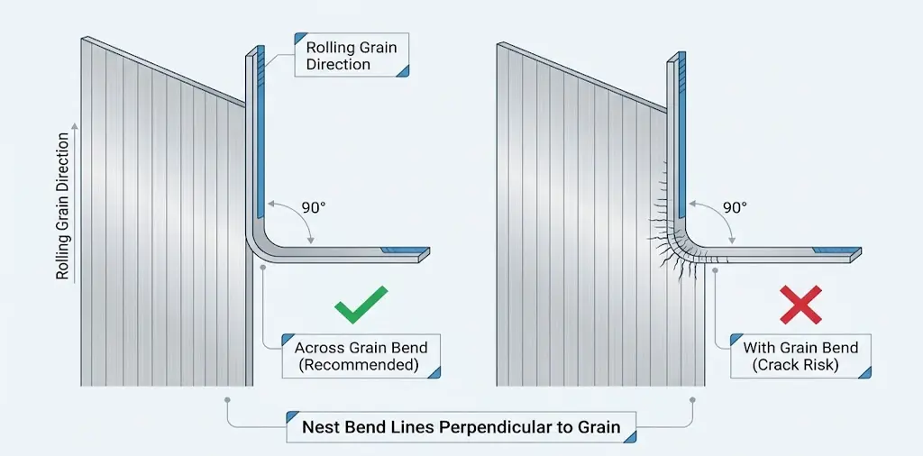
Rolled sheet carries an elongated grain aligned with the rolling direction, and through-thickness ductility across that grain is lower than along it. A bend line parallel to the rolling direction asks the outer fiber to stretch across the weak direction — which is why with-grain bends crack in hard tempers on parts that bend cleanly the other way.
- Nest so bend lines cross the rolling direction. That is a pre-laser decision, which puts it in the quote review, not the setup sheet.
- Where the design forces a with-grain bend, grow the radius rather than hoping; the supplier’s with-grain data is the number to trust.
- On first articles in an unfamiliar temper, test both directions, then write the result on the drawing so cutting and bending inherit it.
Cross-grain nesting can cost sheet yield, and planners sometimes rotate parts back to recover material. If “random” cracks appear after a nesting change, look here first.
Handle Springback Without Coining the Part
Soft tempers recover little; hardened and heat-treated tempers recover considerably more, and larger radii further than tight ones. The measurement-driven workflow is in our springback guide; the aluminum-specific points are these:
- Compensate per temper, not per alloy. 6061-T6 and 5052-H32 of the same thickness behave differently, and lots vary — verify on the first article instead of carrying a steel-era offset in the program.
- Fix the radius before chasing the angle. Overbending a bend already below the temper’s limit adds strain on top of a crack in progress.
- Resist bottoming and coining as springback killers. Bottom bending is workable on softer grades with the right punch geometry, but it is an expert setup, not a production default — for hard tempers the creasing risk and higher force make it the wrong tool, and the crease cannot compensate springback the way it does in mild steel.
Tight Radii, Hems, Finished Sheet and V-Grooving
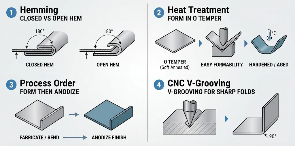
Four situations defeat the standard rules.
Closed hems in hard tempers. A closed hem asks the outer fiber to survive a 180° bend at near-zero radius. 5052 handles it with an appropriate pre-bend; 6061-T6 will not close-hem without cracking regardless of tooling finesse. Realistic options are an open hem, a temper change or a design change — the tooling side is in our hemming and flattening guide.
Form-in-O production. For parts that must be both strong and tightly formed, buy the alloy in O or T4, form it soft, then solution-treat and age it. It works — aerospace shops run it routinely — but it adds heat-treatment cost, distortion risk and a supplier handoff, so it is a quoting-stage decision, never a rescue attempted after T6 parts start cracking. Do not substitute a torch: uncontrolled heating alters heat-treated alloys unpredictably.
Anodized and finished sheet. Anodic layers are hard, brittle ceramics bonded to metal that is about to be stretched, so bending after anodizing crazes the finish on the tension side — sometimes visible, sometimes micro-craze that only shows in service. Form first, then anodize, plate or powder coat.
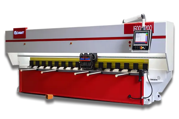
Sharp folds a radius cannot deliver. Some architectural and decorative parts demand a near-zero-radius fold that no safe bending setup can produce. CNC V-grooving removes a controlled depth of material along the bend line, thinning the section that must deform so the fold comes out sharp. The trade-off is real: the groove reduces the remaining section and can affect structural strength, so groove geometry and residual thickness must be qualified against the part’s loads. For panels where a sharp fold and a clean surface line matter more than section strength, that is what our CNC V-grooving machines are built for. V-grooving is not a crack fix — it is a design-stage alternative for a different problem.
Design the Crack Out Before It Reaches the Brake
Most aluminum cracks are decided upstream. Four drawing habits prevent them:
- Specify alloy, temper and thickness — not “aluminum.” A one-word callout lets the supplier ship whatever is in stock, and the temper mix-up it produces is the most common cause of batch-to-batch cracking.
- Define the inside bend radius. Leaving it to the fabricator invites the tightest tooling default.
- Add bend reliefs where bend lines terminate at an edge or intersect, so deformation ends cleanly instead of tearing into the corner.
- Keep holes and cutouts clear of the bend zone; if the design forces the proximity, machine the feature after bending.
When Cracks Still Show Up
If cracked parts reach the bench anyway, resist the reflex to touch the program and run this in order:
- Verify the material, not the label. An H34 pallet delivered where H32 was quoted, or T6 sheet slit into a 5052 job — temper mix-ups are the most common cause of “sudden” aluminum cracking. Check mill certificates against what the program assumes.
- Read the crack’s origin. Mid-radius splitting points at radius or temper; edge-started tears point at burrs, dross or cut-edge condition; a tear into a corner points at a missing relief. The full crack triage table maps each signature to its cause.
- Check nesting history. Cracks that appeared after an orientation change means you have already found it.
- Only then touch tooling and settings, one variable at a time, with coupons from the same sheet.
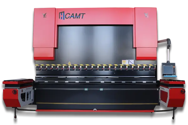
What remains is the machine’s job: holding a validated setup repeatably. A brake that holds programmed depth, compensates crowning and verifies angles in-cycle keeps an approved aluminum setup approved for the whole batch — the property aluminum tests hardest, since lot-to-lot springback drift shows up as angle scatter before it shows up as anything else. Our press brake range runs from economical torsion-bar machines to CNC models with in-cycle angle measurement, and we will review a specific aluminum part against a specific machine before you commit either way.
The Pre-Production Checklist
Material — alloy and temper confirmed against the mill certificate · thickness verified · rolling direction identified · edges inspected.
Tooling — punch nose matched to the target radius · V-die opening derived from the required radius · tooling clean, aligned and rated for the load.
Process — radius agreed at design stage · flat pattern recalculated · test bend from the actual lot · outside surface and final angle checked · approved parameters recorded.
Production — first article checked against the test bend · lots monitored for temper or mill changes · any defect investigated before the batch continues, never by adding force.
The numbers in this article come from the allowances and bend geometry set out in our sheet metal bending guide.
FAQ
Can you bend 6061-T6 without cracking?
Yes — with roughly 2–4× thickness inside radius (verify against your supplier’s bend-test data), cross-grain bends, clean edges, and springback handled by overbending. Cracks in 6061-T6 almost always trace to a radius below the temper’s limit, a with-grain bend or a flawed cut edge.
What is the minimum bend radius for 5052-H32?
Commonly cited starting ranges are about 1–1.5× thickness across the grain with clean edges; the governing value is your supplier’s bend-test data for the actual lot. Along the grain, expect to need more.
Should I use the same V-die for aluminum as for steel?
Only by coincidence. The opening sets the air-bent radius, and aluminum tempers usually demand more radius than a thickness-based 6–8× steel opening produces — so the radius picks the die, and the wider opening costs almost nothing in tonnage.
Does bending along the grain always crack aluminum?
No — it raises the risk, sometimes dramatically, because through-thickness ductility across the elongated grain is lower than along it. Soft tempers may bend with the grain without trouble; 6061-T6 frequently does not. A two-piece directional test on the first article settles it for the lot you are running.
Can I bend anodized aluminum?
You can, but expect the brittle anodic layer to craze on the tension side — sometimes visibly, sometimes only as micro-cracking that appears later. Form first and anodize afterward.
Should aluminum be heated before bending?
Not on the shop floor. Controlled heat treatment is a real process — form-in-O production depends on it — but it belongs to qualified heat-treatment suppliers, not to a torch at the brake. Uncontrolled heating alters heat-treated alloys unpredictably.
Does a CNC press brake prevent aluminum cracking?
No. A CNC control improves repeatability and can automate springback compensation, but it cannot restore ductility the material condition never had. Cracking from a wrong temper, an under-specified radius or a with-grain bend reproduces identically on the most advanced machine.