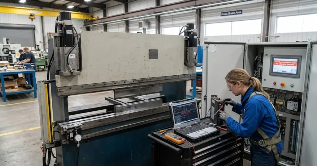
A Y1/Y2 synchronization alarm means the controller has seen the two sides of the ram disagree by more than the window the machine builder allows, and it stopped the cycle because it could not close the gap within its correction authority. That is all the alarm says. It reports a disagreement, not a cause — and the fastest way to waste a shift is to replace parts before you know which side is falling behind and when.
The causes fall into five families: position feedback, hydraulic supply and internal leakage, valve response, mechanical drag or geometry, and the load itself. Which family you are in is usually decided by when the deviation appears in the stroke, not by which side the display names. So the order below is: read the timing, confirm with a couple of inexpensive measurements, then open the hydraulic or electrical system only where the evidence points.
One boundary before you start. This applies to electro-hydraulic CNC press brakes with independent Y1/Y2 axes. Torsion-bar NC machines hold the two sides together mechanically: the part still tapers, but there is no independent Y2 to calibrate, and the investigation is a mechanical one.
What Y1 and Y2 Actually Are
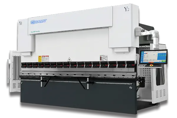
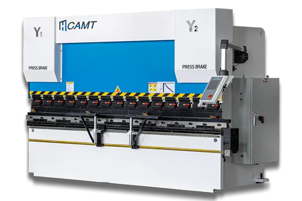
On an electro-hydraulic CNC press brake, Y1 and Y2 are the left and right ram position axes. Each side has its own cylinder, valve and linear scale, and the controller compares actual against commanded position continuously, trimming both valves to keep the ram parallel. That is the arrangement the industry literature describes for active leveling: a high-speed controller, linear transducers and proportional valves, with two-axis control giving left-to-right parallelism and four-axis control adding front-to-rear (The FABRICATOR).
That closed-loop layout is only one of the architectures sold under the same label, and “synchronization error” means something different on each:
| Machine type | How the sides are held together | What a sync error means here | First place to look |
|---|---|---|---|
| Hydraulic, closed-loop Y1/Y2 | Independent cylinders, valves, scales, cross-monitored | A real axis disagreement the control could not close | Valve response and scale signal |
| Hydraulic, torsion bar | One circuit plus a mechanical link | Usually a taper complaint, not an alarm; the link is wearing | Bar, bushings, bed level |
| Hybrid (servo pump) | Closed-loop Y1/Y2 on a servo-driven pump | Same as closed-loop, plus pump and pressure dynamics | Pressure balance, then valves |
| Servo-electric | Twin screws, servos and encoders | Drive-level position mismatch | Encoder, screw and nut, coupling |
Two consequences follow. Confirm which architecture you own before accepting advice, including this advice. And on a closed-loop machine, write the deviation value down — it tells you how far apart the sides were when the control gave up, and most shops never record it.
Read the Timing Before You Read the Parts
A worn piston seal, a dirty scale and a part loaded on one end of the bed can all produce the same code. What separates them is when the deviation grows, and whether it needs load to appear. The cost profile differs too: an alarm at start-up costs you a shift, while a deviation that only shows under load costs you parts, tooling and eventually gibs.
| When the deviation appears | What it usually means | First check |
|---|---|---|
| At power-up, or the machine will not reference | Position reference lost; axis moved while powered down; scale signal missing | Reference return procedure, scale cable, readhead |
| During rapid approach, dry cycle, no material | Valve spool sluggish or sticking; air in the circuit; unequal pilot pressure | Valve response and oil condition, then bleed |
| At the slowdown or penetration phase | Low-flow behaviour, seal stiction, drag on one side | Gib clearance and lubrication; valve null |
| Only at the bottom, only under load | Internal bypass, eccentric load, tonnage beyond one side's share | Cylinder drift test, load audit |
| On decompression or the return stroke | Piston seal bypass, counterbalance or return valve | Drift test with the pump off |
| Only after an hour or two of running | Viscosity drop, valve null drift, thermal growth at the scales | Temperature comparison, warm-state baseline |
| Only on long parts, or with tooling at one end | Load distribution, bed twist, uneven gib wear | Tonnage and tooling-length audit |
| Random, worse when a welder is nearby | Electrical noise, grounding, damaged scale cable | Shielding, grounding, cable routing |
Misdiagnosis concentrates in the bottom rows. A deviation that creeps up over weeks is not a valve problem, and one that appears when another machine starts is not a hydraulic problem at all.
The Seven Causes and Their Fixes
Work the list in the order the timing table pointed at, not from the top. Every item below assumes the machine is isolated and the ram is blocked before anyone reaches into the die area.
1. Encoders, scales and feedback wiring

The scales tell the controller where each side of the ram is. If one signal is intermittent, the loop keeps correcting toward a position that is not real, and the ram either hunts or drifts out of parallel.
Common causes: dust, oil mist or metal particles on the strip; a loose mounting bracket; a damaged readhead or scale; a crushed or poorly seated cable; electrical noise on the signal.
How to fix it:
- Open the axis monitoring screen and compare Y1 and Y2 actual values, then watch both while the ram stands still. A reading that jumps or freezes with no command is a feedback fault, not a hydraulic one.
- Clean the strip and readhead only by the manufacturer’s method, and check the gap and bracket torque before touching any parameter.
- Check the cable along its route for crushing, strain and shield termination.
- Replace damaged components, then perform the full referencing and calibration procedure — never shift an encoder mount or edit its offset to make the number look right.
Inspection and cleaning can be done in-house if training covers it. Signal checks, readhead replacement and any electrical-cabinet work belong to a qualified technician or electrician, with the machine isolated.
2. Hydraulic supply and internal cylinder leakage
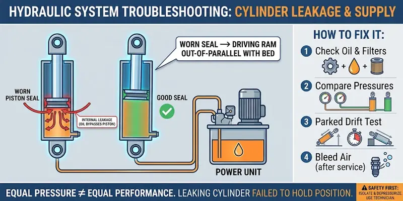
Both cylinders draw from one power unit, which does not mean they see identical flow or identical load. A worn piston seal is the one that matters most, because oil can bypass the piston without a drop appearing on the floor.
How to fix it:
- Check oil level, oil condition and filter history. Oxidised oil forms varnish, and varnish “can cause valves (especially proportional and servo types) to stick” while also raising temperature (Machinery Lubrication).
- Compare pressure on both sides at the same point in the cycle, under the same load, with calibrated gauges.
- Run the parked drift test: pump off, ram raised, watch each side. Movement on one side is that cylinder leaking past the piston — the documented behaviour is that a two-cylinder ram can “drift far enough on that side so that it becomes out-of-parallel with the bed” (The FABRICATOR).
- If air is suspected after a service event, bleed per the manufacturer’s procedure and re-check at low speed before running production.
Equal pressure does not prove equal performance: a leaking cylinder still builds pressure, it just fails to hold position under load. Never crack a fitting on a pressurised circuit — isolate and depressurise first, and leave seal replacement to a hydraulic technician.
3. Proportional and servo valve response
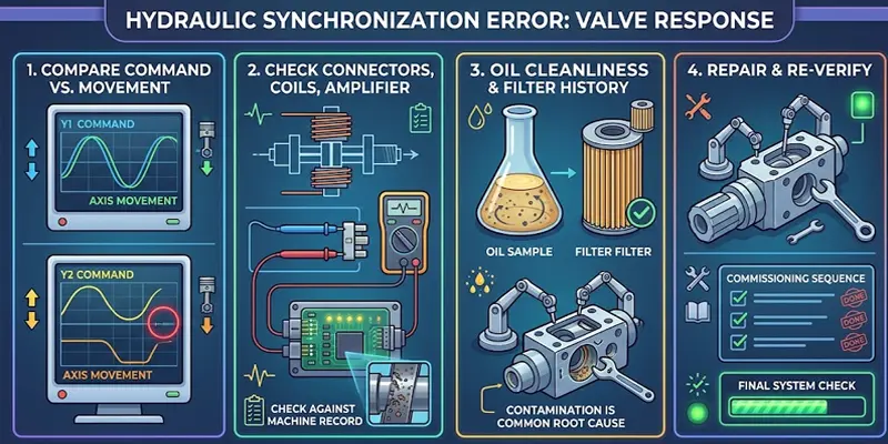
The valve is where a command becomes motion. If one spool is slow, sticky or slow to return, that side lags and the loop saturates trying to catch up. It shows most clearly at the transition from rapid approach to working speed, where flow demand changes fastest.
How to fix it:
- Compare Y1 and Y2 valve commands against actual movement — a command that rises while the axis does not follow is a valve or supply problem, not a control problem.
- Check connectors, coil condition and amplifier settings against the machine record.
- Review oil cleanliness and filter history; contamination is more often the root cause than the valve.
- Clean, repair or replace per the manufacturer’s instruction, then re-verify through the approved commissioning sequence.
Valve null, gain and balance are legitimate adjustments, but only with the builder’s procedure and only after the original values are recorded. A machine tuned by three people over five years is its own cause of synchronization error.
4. Electrical interference and damaged cables
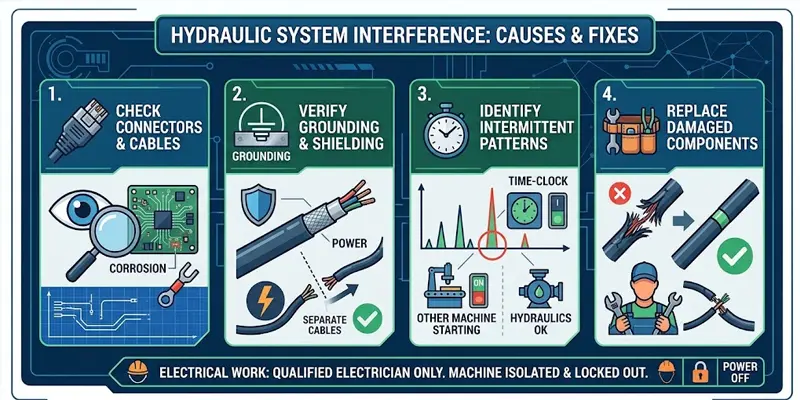
Scale signals are low level and the environment is hostile: drives, VFDs, welders, marginal grounding. The controller then corrects toward bad data, which looks identical to a hydraulic fault from the outside.
How to fix it:
- Check connectors for corrosion, loose terminals and moisture, and check cable routing against the electrical drawings.
- Verify grounding and shield termination, and separate feedback cables from power cables where the design permits.
- Look for an intermittent pattern — if the deviation appears when another machine starts, stop looking at the hydraulics.
- Replace damaged cable or connectors and retest before any parameter change.
Electrical work is for a qualified electrician, with the machine isolated and locked out.
5. CNC parameters and Y1/Y2 calibration
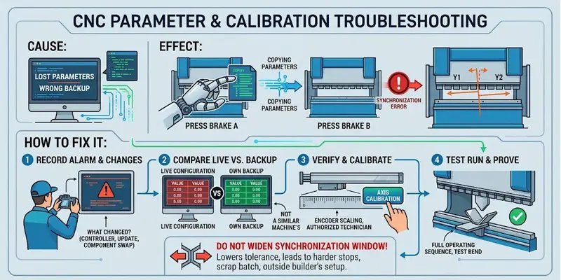
Parameters are machine-specific. Lost, restored from the wrong backup, or copied from another press brake, they will produce a synchronization error on a machine whose mechanics and hydraulics are sound.
How to fix it:
- Record the exact alarm, then ask what changed: controller work, a software update, a restoration, a component swap.
- Compare the live configuration against the machine’s own parameter backup, not a similar machine’s.
- Verify reference positions and encoder scaling, then have an authorised technician run the axis calibration.
- Prove it through the full operating sequence and a test bend before releasing the machine.
Do not widen the synchronization window to clear an alarm. A wider window does not restore synchronization; it lowers the threshold at which the machine admits it has lost it, and the next event is a harder stop or a scrapped batch. On machines where that limit forms part of the validated configuration, changing it also takes you outside the builder’s setup — a maintenance decision with consequences well beyond part quality.
6. Mechanical drag, guideway wear and ram upset
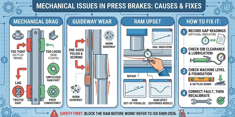
Mechanics enter twice: drag that makes one side lag, and geometry that makes the two sides measure differently even when the control is behaving.
A ram permanently deformed in the middle — from concentrated load or long runs at full tonnage — will not measure parallel whatever the scales say, and this is where a dial indicator earns its place. Swept along the ram-to-bed gap with the ram closed, a needle that drifts steadily in one direction across the bed means the ram is out of parallel and can be corrected with the tilt adjustment; a needle that moves one way toward the centre and back the other way indicates upset, which requires repair rather than adjustment (The FABRICATOR).
Gib clearance belongs in the same check. Too tight, and the gib acts as a brake on one side so the ram twists as it travels; too loose, and the ram floats, which shows up in flange width and angle consistency. Published guidance puts many machines at 0.001 to 0.002 inch, seldom beyond 0.006 to 0.008 inch, with the manufacturer’s figure taking precedence (The FABRICATOR).
How to fix it:
- Sweep the gap with a dial indicator at several points and record the readings before adjusting anything.
- Check gib clearance, lubrication along the full length, and one-sided polish or scoring.
- Check machine level and foundation. A long machine on settled shims carries a twist that will not respond to Y correction.
- Correct the mechanical fault first, then recalibrate — never force alignment with valve or stop adjustments to hide the symptom.
Block the ram before reaching under it. Beam motion and the hazards around it are what ISO 6909:2026, the current standard for press brakes, addresses for hydraulic and servo-drive machines (ISO).
7. Off-center loading and excessive tonnage

Tooling at one end of a long bed, a short heavy part on a wide machine, or two operations at once all load one cylinder harder. Modern controls shift pressure between the cylinders to compensate, but only within the machine’s capacity and the loop’s authority. Beyond that, the ram tilts and the alarm is reporting a fact. Repeated off-center work also has cumulative structural consequences: poor consistency, premature tool wear and stress on the frame (The FABRICATOR).
How to fix it:
- Note whether the error appears only on certain jobs, and where the part sits on the bed.
- Check required tonnage against the machine’s capacity for that length and die, not against its headline rating.
- Re-position the part or redistribute tooling where the process allows.
- Check crowning separately from sync. If the two sides track each other and the angle still varies along the length, you are in deflection territory, not synchronization — the same fork covered in why parts from one batch have different bend angles.
Diagnosing It in Five Steps
Step 1 — Record before you reset. The exact alarm text, whether it happens at startup, approach, working speed or return, whether the machine is loaded, and what changed recently. Do not clear the code until it is written down; it is the only evidence you get for free.
Step 2 — Take a three-position deviation record. Y1 and Y2 values at top of stroke, mid-stroke and bottom, cold and again at operating temperature. If the deviation exists with no material in the die, the load is not the cause. If it only appears loaded, everything upstream of the die is probably fine.
Step 3 — Confirm the geometry. Dial indicator sweep along the ram-to-bed gap, then gib clearance at both ends. This separates a real mechanical fault from a control that believes it has one, and it takes less time than reading this section.
Step 4 — Park it and watch. Pump off, ram raised: any drift on one side is bypass. Then compare cylinder body temperatures with an infrared thermometer after equal duty; a persistent difference is a hydraulic finding, not a control finding.
Step 5 — Fork, then calibrate last. Unstable feedback points to encoders and wiring. Stable feedback with one side lagging points to valve, supply, cylinder or drag. Only after that: reference return, parallelism check at more than one stroke position, and a three-point test bend at both ends and the centre. Calibrating before steps 3 and 4 is how a real fault gets buried under a fresh offset.
The Checklist, With Who Does What
| Inspection item | What to check | Who |
|---|---|---|
| Alarm history | Exact code, stroke phase, loaded or dry, recent work | Operator / technician |
| Y1/Y2 feedback | Actual values at three positions, cold and warm; any jump or freeze | Qualified technician |
| Scales and readheads | Strip condition, gap, bracket torque, cable | Qualified technician |
| Electrical | Cable damage, grounding, shielding, connectors | Qualified electrician |
| Hydraulic oil | Level, condition, filter history | Hydraulic technician |
| Cylinders | Parked drift, pressure comparison, seal condition | Hydraulic technician |
| Valves | Command vs actual, coil, amplifier settings, contamination | Hydraulic technician |
| Mechanics | Gap sweep, gib clearance, lubrication, level | Maintenance technician |
| Parameters | Machine-specific configuration against backup | CNC service engineer |
| Verification | Reference return, calibration, test bends at three points | Authorised service personnel |
Keeping It on the Schedule
Most of what fills this article is cheaper to prevent than to diagnose, and the interval side belongs in your scheduled maintenance routine rather than in a fault investigation — our maintenance checklist covers the cadence. If you take one habit from here, take the record: a single page per machine, monthly, with the three-position deviation cold and warm, oil temperature, pressure on both sides, gib clearance at both ends, and three-point test bend angles on the same material every time.
Two months of that tells you whether a deviation is drifting, whether it is temperature-linked, and whether the last calibration held. It also turns a support call from “the machine has an error” into “the deviation at the bottom has doubled in six weeks, and only when the oil is warm” — which is a diagnosis, and usually a same-day one.
When to Call a Service Engineer
Arrange support when the alarm returns after a reset, when the ram visibly tilts, when one cylinder responds noticeably slower than the other, when feedback stays unstable after you have checked accessible connections, when synchronization is lost under pressure, or when the problem began right after a controller, encoder or hydraulic repair. Continuing to run costs tooling, parts and frame life, in that order.
Before you call, collect the machine model and serial number, controller type and software version, the exact alarm message, the three-position readings, and a short video of the behaviour. That set usually narrows it to one family before anyone travels, and you can send it through our contact page if email is easier to track.
Choosing a Machine That Makes This Error Rare
No design eliminates synchronization error, because every design depends on wear parts: seals, valves, scales, gibs, screws. What differs is how early the machine tells you, and how much of the diagnosis it hands you.
Three design choices matter more than the brochure numbers. Independent closed-loop control on each side, with real feedback per side rather than a single sensor and an assumption. Feedback hardware suited to the environment — magnetic scales tolerate oil mist, dust and vibration better than exposed glass in most shops, and signal stability matters more than resolution. And diagnostics you can actually read: a controller that logs Y1/Y2 history and alarm context lets a technician work from evidence instead of from a site visit.
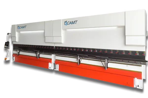
The Smart series is built around the first of those: closed-loop electro-hydraulic servo control on Y1/Y2, Italian GIVI magnetic scales at 1 µm resolution, multi-point mechanical crowning kept separate from the synchronization loop, and a choice of DELEM, Cybelec, ESA or the in-house control. It runs 40–600 tons over 1.6–6 m, which covers the work where sync faults hurt most — long parts, thin material, tight angle tolerance.
If you are already living with a machine that trips, our technical support team reads controller logs and parameter records remotely, and can often tell from a deviation trend whether you are looking at a scale, a valve or a seal before a technician is booked.
This check sits inside a wider calendar. The press brake maintenance checklist sets the daily, weekly and annual intervals that surround it.
Frequently Asked Questions
Can I keep running with a Y1/Y2 alarm?
No. An unresolved synchronization fault means the two sides of the ram are further apart than the machine was designed to tolerate, and those loads go into your tooling, your gibs and your frame. Do not bypass the alarm and do not run a visibly tilted ram. Resume only after the cause is corrected and the machine has passed referencing, calibration and a test bend.
Why does it only appear on thick or long parts?
Thin, short parts do not demand enough force to expose it. A deviation that needs load points at bypass, pressure imbalance or load distribution: the machine can hold position when it is barely working and cannot when one side carries more than its share. Start with the parked drift test and a tonnage audit rather than with parameters.
The display says Y1 and Y2 are level, but the parts taper. How?
The scales measure the ram where the readheads sit, not at the tool tip, and they only measure at two points. A scale bracket that has shifted, a ram upset in the middle, a twisted bed or a punch not seated at one end can all produce a taper on a machine whose readout is perfectly happy. The dial indicator sweep answers it in ten minutes.
How often should Y1/Y2 be checked?
Follow the manufacturer’s schedule, and add a check after anything that changes geometry or feedback: a move, a re-level, a scale or valve replacement, a seal replacement, a hard crash. In between, the monthly three-position record catches drift long before it becomes an alarm.
Is this maintenance or a breakdown?
Depends where you are on the curve. Dirty oil, a contaminated scale and a dry gib are maintenance misses that turn into breakdowns. A failed readhead, a leaking seal or a worn screw are component failures. The distinction matters because the first group is cheap to prevent, the second cheap to catch early — and a repeat failure after a repair usually means the first group was never addressed.
Can an older torsion-bar machine be upgraded to independent Y1/Y2 control?
Sometimes, and it depends on the frame, the manifold and the condition of the mechanical link. Retrofitting independent feedback and proportional control onto a machine that was never designed for it is a bigger project than a controller swap, and on a worn frame it can cost more than the accuracy it buys. If the geometry is sound, a control and valve upgrade is worth evaluating; if the bar and gibs are worn, fix the mechanics first.