A rough or uneven edge on a laser-cut part is not a mystery, and usually not a sign the machine is failing. The cut face records how steadily molten metal was produced and swept out of the kerf; every irregularity on it points to a specific layer: focus, speed-power balance, gas delivery, machine state, or the material.
The pattern matters more than the roughness: two edges with the same measured roughness can have different causes, so the fastest diagnostic step is to look at the face before touching any setting. This article walks through each layer in checking order, explains how to read the roughness signature, and clarifies when an edge is normal for the process.
Striations Are Normal; a Rough Edge Is a Signal
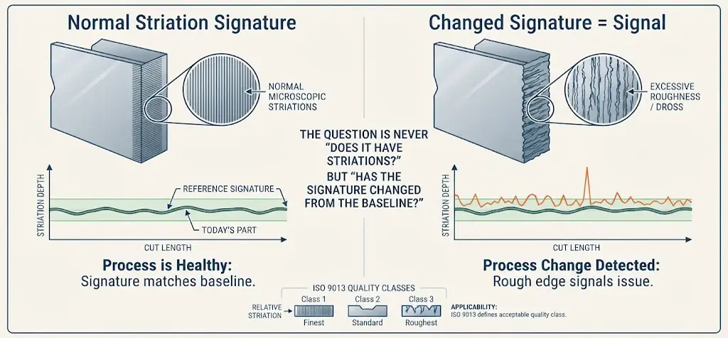
Every fusion-cut laser edge carries striations — the fine vertical lines left by the repeating melt-and-ejection cycle — a feature of the process, not a defect. Even edges marketed as “striation free” are, under magnification, still covered in microscopic striations, as a peer-reviewed study of fiber-laser oxygen cutting concluded after measuring edges across the full speed range (J. Powell et al., Optics and Lasers in Engineering, 2011 — 2 kW fiber laser, oxygen assist, thin-section mild steel; conditions of that experiment, not a general rule).
So the practical question is never “does my edge have striations?” It is: has the signature changed from the baseline this machine established? A first-off sample, cut when the machine was known good, is the reference: if today’s parts match it, the process is healthy; if the signature has changed, the change itself is the diagnosis.
Acceptable is application-defined: an edge hidden inside a weldment tolerates more texture than a cosmetic show surface. For contractual work, the criterion belongs on the drawing as a quality class — “cut clean” settles nothing if parts are disputed. The class system under ISO 9013 is covered in our ISO 9013 laser-cut edge quality guide (camtmachine.com/iso-9013-laser-cutting); the underlying vocabulary — kerf, focus, striation, dross — is defined in our laser cutting terms glossary.
Read the Cut Face Before You Touch a Setting
Operators who fix edge problems fastest treat the cut face like a chart recording: the direction, depth and distribution of the roughness encode which layer of the process is misbehaving. Work down this table, change one variable at a time, and re-cut a test coupon from the same parent sheet after each change.

| Roughness signature | Check this first | What it tells you |
|---|---|---|
| Fine, uniform striations over the whole face, matching your first-off sample | Nothing — compare against the sample | Normal process texture, not a fault |
| Smooth near the top, roughness deepening in the lower third | Focus height relative to material thickness | Focus outside its window — kerf geometry is the bottleneck |
| The face leans — the cut is beveled rather than perpendicular to the sheet | Focus height, then beam-to-nozzle alignment | Kerf geometry drifting; the verticality deviation ISO 9013 measures |
| Roughness on one side of the face only | Nozzle bore condition, then beam-to-nozzle centering | Asymmetric gas flow — consumable or alignment, not a parameter |
| Deep striation bands interrupting an otherwise smooth edge | Surface condition of the incoming sheet | Loose mill scale flaking into the melt pool |
| Roughness varies with position on the sheet, direction unchanged | Sheet flatness, table support, height-control response | The sheet rides or dips under the head — a presentation problem |
| Roughness that crept in mid-shift or after maintenance | Protective lens condition, gas gauge versus recorded baseline | Machine-state drift, gradual enough to miss |
| Deep drag lines plus incomplete penetration at the bottom | Speed relative to power for this thickness and gas | Genuine overspeed — the one signature that justifies slowing down |
| Roughness changes with each new batch or heat | Parameter and batch log; compare consecutive heats | Incoming material variability — tune per batch, don't chase the machine |
One habit ties the table together: never judge roughness from a single part, and inspect away from the pierce point and the cut-out end — the two zones that are naturally worst on any edge.
Focus Position First
In a full factorial experiment on fiber laser fusion cutting — power, focal plane position, gas pressure, nozzle stand-off and nozzle diameter varied on 10 mm AISI 304 stainless with nitrogen (Mahrle, Borkmann and Pfohl, Materials 14(10):2669, 2021, Fraunhofer IWS; conditions of that study) — focal plane position came out as the most decisive factor, while the gas parameters showed only secondary effects on bottom-edge roughness. The mechanism reorders the whole sequence: focus sets the shape of the kerf, and kerf geometry — more than any knob on the gas supply — governs the shear stress that strips melt off the cut face.
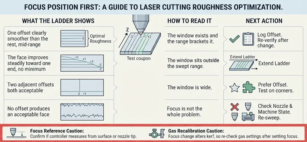
That is why roughness work starts with a focus ladder, not a gas bottle: cut short test lines across a range of focus offsets on adjacent coupons from the same parent sheet — never re-cut an already-cut plate — inspect each face, and read the ladder:
| What the ladder shows | How to read it | Next action |
|---|---|---|
| One offset clearly smoother than the rest, mid-range | The window exists and the range brackets it | Log the offset with the job; re-verify after any condition change |
| The face improves steadily toward one end, no minimum | The window sits outside the swept range | Extend the ladder in the improving direction |
| Two adjacent offsets both acceptable | The window is wide | Prefer the offset that also survives corners and small holes |
| No offset produces an acceptable face | Focus is not the whole problem | Check nozzle condition and machine state before re-sweeping |
Two cautions. Controllers report focus differently — some from the surface, some from the nozzle tip — so confirm against the machine manual before transferring offsets. And because a focus change alters kerf width, gas settings that produced good edges before may no longer match; re-check the gas side after settling focus, not before.
Both too slow and too fast roughen, edges slow down only for drag lines

Common advice says a rough edge means you are cutting too fast; measured data says otherwise. In the Powell study cited above, roughness fell to a minimum at an intermediate speed well below the maximum, then rose on both sides of it. At low speeds the melt is cooler and more viscous and does not sweep cleanly; at high speeds the melt layer thickens and mass flow down the cut front grows, and the edge roughens for a different reason. Both failure modes look “rough” to the eye — which is why single-direction speed trials oscillate between two kinds of roughness.
The reliable marker of genuine overspeed is a combined signature: pronounced drag lines down the face plus incomplete penetration at the bottom of the cut. When both appear, the process is outrunning the melt front, and a speed reduction — or a power increase, if reserve exists — is justified. If the edge is rough but the cut separates cleanly and fully, the cause almost always lies elsewhere in the table above, and slowing down often makes things worse: reduced speed raises melt temperature rather than cleaning the edge. (For why the bottom of a thick kerf starves first, see our guide on why a fiber laser may not cut through — camtmachine.com/laser-not-cutting-through.)
Treat a speed adjustment like a focus change: one step at a time, a fresh coupon from the same parent sheet, a record of each step. If roughness persists across the whole usable speed range, the window has collapsed — pointing back to focus, nozzle or machine state.
Nozzle condition, alignment, and steady gas flow ensure clean melt ejection

Assist gas does not polish the edge; it strips melt off the cut front, and the research is specific about how. In those factorial trials, measured roughness correlated strongly with the rear-directed shear stress of the gas flow along the kerf wall — the boundary-layer behavior, not the gauge pressure (Borkmann, Mahrle and Beyer, Procedia CIRP Vol. 74, 2018; fiber laser fusion cutting of 10 mm AISI 304, gas pressure and nozzle stand-off among the control factors). The follow-up conclusion is sharper: kerf geometry influences that shear stress more than the gas parameters do — hence the focus section comes first.
The nozzle is the exception that earns its own check: a bore that is worn, ovalized or spatter-loaded, or a nozzle off-center to the beam, distorts the flow so one side of the kerf is flushed harder than the other — the one-sided signature above. The quickest shop test is a square cut in four directions on the same sheet: if one travel direction consistently cuts worse, beam-to-nozzle alignment is the suspect, not the program. Nozzle condition also degrades slowly — the edge worsens day by day until someone inspects the bore — so keep nozzles and lenses on a replacement schedule; routine is covered below.
Gas purity and gas selection shift the whole process, not the flow pattern. Their effects — oxide with oxygen, color variation with drifting purity — are covered in our assist gas comparison (camtmachine.com/laser-cutting-assist-gas). If roughness arrived with a gas-supply change — a new cylinder bank, a generator coming online, several machines drawing at once — treat purity stability as the suspect. And read pressure under actual cutting flow, not the regulator’s static reading: a supply healthy on the gauge can still starve the kerf once the valve opens.
When the Cause Is Not a Setting
Some roughness has no parameter behind it. The protective lens is the most common example: each layer of spatter absorbs and scatters a little of the beam, so energy at the kerf drifts from the programmed value while every setpoint looks correct. Roughness creep across a shift, or shortly after maintenance, belongs here — as do beam-path alignment and mechanical wear, where the beam no longer lands where the program believes it does.
Because these components fail gradually, compare against a recorded baseline: what did the edge look like right after the last verified-good state? Our fiber laser machine components guide explains how each element of the optical path degrades and what inspection intervals keep it visible.
Nozzle Height, Sheet Support and Motion Stability
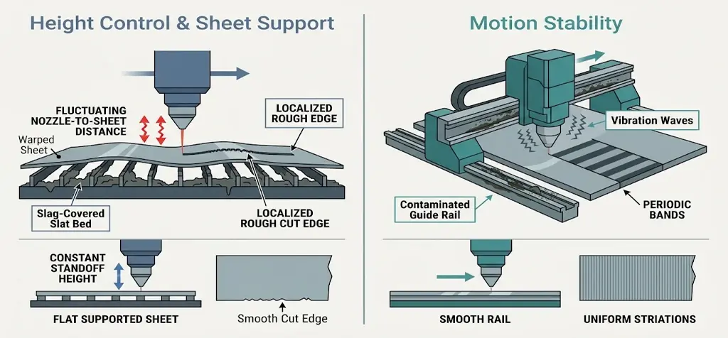
Two presentation problems produce roughness no parameter explains. The first is height control: nozzle-to-sheet distance must stay constant, and it does not when the sheet is warped, the table carries slag, or the capacitive sensor responds sluggishly. Thin sheet can lift from residual stress or thermal deformation, and sections cut while it rides high come out rougher. If roughness follows an area of the sheet rather than the cutting direction, check flatness, support and height sensing before touching a setting.
The second is motion stability: guide-rail contamination, worn drives or vibration at speed produce periodic irregularities — a rhythm the melt cycle never makes. Uniform striations belong to the process; periodic bands belong to the machine. Do not compensate by changing power or speed: that hides the fault while scrap accumulates. Both checks belong in the maintenance routine below.
Material and Batch Effects
The incoming sheet leaves its own fingerprints on the edge. Loose or poorly adhered mill scale is the classic case: flakes detach, ride into the melt pool, and gouge the forming face — the banded signature in the table above. Batch-to-batch variation in chemistry and surface finish does the same at finer scale; on some combinations the difference between two heats of nominally identical grade shows in the edge first.
The practical response is attribution. When roughness follows the batch — clean edges yesterday, rough ones today, same program — the material changed; the correct action is a small coupon-based re-tune recorded against that batch, not a hunt through the machine. When it follows the machine regardless of batch, the earlier sections apply. Our fiber laser cutting troubleshooting guide (camtmachine.com/fiber-laser-cutting-troubleshooting) lays out the full attribution framework across dross, burrs and rough faces; aluminum-specific behavior is handled in our laser cutting aluminum guide (camtmachine.com/laser-cutting-aluminum).
What Rough Edges Cost You Downstream
An edge that leaves the table rough rarely stays merely cosmetic. Rough faces grip grit, resist coating in the valleys, and add deburring labor that was never in the quote. In fatigue-loaded parts the striation valleys act as stress raisers — a characterization the cutting literature carries down even to micro-scale tube work (AISI 316L fiber-laser micro-cutting roughness study). Uneven edges also complicate fit-up: parts nested to precise coordinates can still assemble poorly when mating faces carry inconsistent texture or clinging dross — a defect with its own diagnosis in our laser cutting dross guide (camtmachine.com/laser-cutting-dross).
This is also why edge quality belongs at quoting time: the acceptance class on the drawing determines the speed a job runs at, the gas route it needs, and whether finishing follows the table — pricing without it is how shops pay for finishing out of margin.
Keeping Edges from Drifting Back
Prevention costs less than diagnosis. Keep a validated parameter record per material, thickness and gas combination, changed only after a controlled coupon test — that stops re-tuning at every order change. Put nozzles and protective lenses on an inspection schedule driven by operating hours and piercing frequency, replacing them against the manufacturer’s criteria instead of waiting for a visible defect; our spare parts and consumables service supplies the matched items. Clean the table and replace worn slats — slag distorts sheet support and feeds the height-control problem above. Check the gas route — regulators, filters, connections — on a schedule, not after a defect. And book periodic beam alignment; our maintenance and upgrades service restores the baseline once drift has accumulated.
When to Stop Tuning and Escalate
Most rough-edge complaints resolve inside the layers above. Escalate when the evidence says the window no longer exists: the edge degraded and stayed degraded with settings verified against the baseline, no focus-ladder position works, roughness persists across speeds and batches, or the machine cannot reproduce an edge it once produced. At that point the remaining variables are configuration and machine condition — a structured conversation with the equipment supplier, not more knob-turning.
Bring the right evidence and the conversation shortens: material grade, thickness and surface condition; the gas route and recorded parameters; coupons from the same parent sheet; photographs of the edge top, middle and bottom; and the current nozzle and protective lens in the machine. If the suspicion is that configuration itself limits the edge — beam platform, optical grade, or a material such as aluminum or copper where suitability must be confirmed rather than assumed — the confirmation belongs in writing from the equipment supplier.
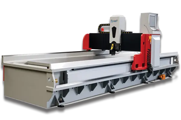
The platform also shapes the edge a shop can hold as standard. An open-type single-table machine such as the ULF series fiber laser cutter and an enclosed exchange-table machine such as the ULE series fiber laser cutter differ in how easily a stable environment — clean air, protected optics — is kept around the cut; our laser cutting machine category page shows the full range. The model sheet for the ordered configuration governs every specification question; family descriptions are not spec tables.
Rough-edge diagnosis is a support conversation as much as a technical one. Our technical support service handles exactly this escalation path — parameter logs, remote review, configuration checks — and if you would rather walk through your signature with an engineer before adjusting anything, contact our team with the evidence package above.