Dross and burrs are two of the most common edge-quality problems in fiber laser cutting. They leave unwanted metal residue along the bottom or sides of a cut, making parts difficult to assemble, weld, paint, or finish. For metal fabrication shops, these defects mean more than poor appearance: they increase deburring labor, slow production, raise operating costs, and sometimes cause finished parts to fall outside dimensional or quality requirements.
The good news is that most laser cutting dross and burr problems can be traced to identifiable process conditions. Cutting speed, laser focus position, assist gas pressure, nozzle condition, material quality, and optical performance all influence how effectively molten metal is removed from the kerf.
This guide explains how to identify different types of dross and burrs, understand their causes, and troubleshoot them systematically. Whether you are cutting carbon steel, stainless steel, or aluminum, you will learn how to improve laser cutting edge quality and reduce unnecessary secondary processing.
Dross formation depends on the force balance at the melt exit
Dross is easier to work on as a balance of forces on the melt film at the exit than as a list of parameters. A 2025 preprint formalises exactly that — a dimensionless Dross Ejection Index setting expulsion against retention, mapped to measured dross area through a threshold curve (Abbas et al., Research Square preprint, posted 8 December 2025, not yet peer reviewed).
Pushing melt out
- Gas shear at the exit, set by momentum rather than the regulator reading. A static gauge says nothing about what the jet does inside the slot.
- Recoil pressure from vaporisation at the cut front — why a tighter spot can help when nothing else changes.
- Exothermic heat, with oxygen only: the reaction adds energy downstream of the focus, keeping the melt fluid and lowering the pressure needed to clear it.

Holding melt in
- Viscosity, which rises steeply as the melt cools and is alloy-specific. Chromium oxides in stainless are the textbook case.
- Gravity, which helps downward but lets melt pool and freeze at the lowest point of the exit.
- Surface tension, which pulls the bead into a sphere and anchors it — why dross is round, and why an existing bead resists the jet.
- Convective cooling by the gas itself. Usually left off the list, and the reason pressure is self-limiting: more pressure buys shear and pays for it in cooling, thickening the melt and raising retention at the same moment.
That last point is the practical core. The same jet supplies both forces, so there is an optimum rather than a direction. The experiment agrees: across five factors and 32 runs, power took about 45% of the effect on dross area, focus 39%, speed 7%, frequency 6.4%, pressure 2.7% (same preprint, stainless 201, image-measured dross area). Its best fit explained only about 28% of the variance — worth reading twice, because dross is threshold behaviour, not a slope you can creep along.
Diagnose laser dross by reading bead patterns before altering parameters
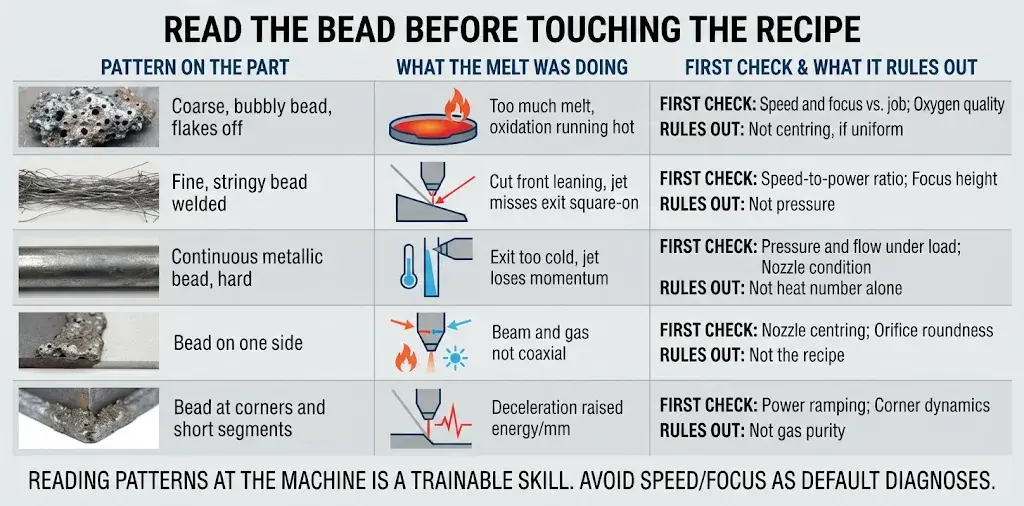
The morphology is data. Each pattern points at one term in the ledger and, just as usefully, excludes two or three others before you spend an afternoon on test cuts.
Shops call the first two rows low-speed and high-speed dross. Useful shorthand, poor diagnoses: hardness is not a speed signature, because adhesion tracks oxidation and alloy — a nitrogen bead on stainless can be harder to remove than an oxygen bead on steel at the same nominal speed error.
Nor is lowering speed the correction for either row: it adds heat per millimetre and disturbs the evacuation flow, so the bead often worsens before it improves. One-sided dross is the most misdiagnosed pattern here, because it looks like a focus error and adjusting focus moves the bead enough to feel like progress. It is geometry. Corner dross is control dynamics, and it gets worse the harder you chase it with feed override.
Reading the five patterns at the machine is a trainable skill, and the difference between a shift that stops after two parts and one that stops after forty (operator training on bead recognition).
Burrs form when weak exit energy and gas momentum pull the last ligament
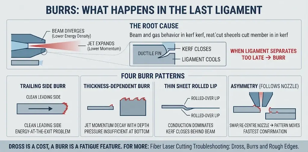
A burr is made at the very bottom of the kerf, when the beam has passed and the remaining ligament has to separate. Two things work against you there: the beam has diverged, so energy density at the exit is the lowest in the whole cut; and the jet has expanded into the slot, so momentum per unit area is at its lowest too. If the ligament cools and the kerf closes before it melts free, the material is pulled rather than cut, and what is left is a ductile fin.
That explains the patterns that confuse people:
- Burrs on the trailing side of a contour, clean on the leading side are an energy-at-the-exit problem, not alignment.
- Burrs that appear as the part gets thicker are jet-momentum decay with depth: the pressure that cleared a thin kerf arrives at the bottom of a thick one with nothing left to spend.
- Burrs on thin sheet are a different animal: conduction dominates, the kerf closes behind the beam, and the result is often a rolled-over lip rather than a fin.
- Burrs that follow the nozzle rather than the part are asymmetry — swap or re-centre the nozzle and the pattern moves with it, which is the fastest confirmation available.
Dross is a finishing cost that can be quoted and scheduled. A burr on a loaded part is a fatigue feature, and that argument belongs to the wider picture in Fiber Laser Cutting Troubleshooting: Dross, Burrs and Rough Edges.
Assist gas type and kerf delivery decide dross before parameters
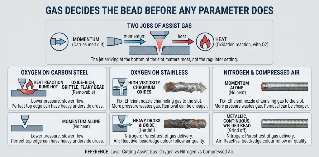
Gas does two jobs, and only one of them is on the dial. It supplies the momentum that carries melt out of the kerf, and — with oxygen — it supplies heat through the oxidation reaction itself. The regulator is the wrong instrument for both, because the jet that matters is the one arriving at the bottom of the slot.
Oxygen on carbon steel. The reaction supplies heat downstream of the focus, which is why oxygen cutting runs at lower pressure and slower flow than nitrogen cutting of the same thickness. The bead is oxide-rich, brittle and flaky, usually removable with a scraper — and a cut that looks perfect on top can carry a heavy bead underneath when the reaction runs hotter than the jet can clear.
Oxygen on stainless is a different problem. TWI puts the cause precisely: low-pressure oxygen cutting forms dross and oxide because of the high viscosity of the chromium oxides produced, and the fix was not more pressure but a nozzle that channelled gas into the slot efficiently enough to reach the momentum dross removal needs (TWI, dross-free laser cutting of stainless steel). If gas is not being delivered into the kerf, raising supply pressure mostly wastes gas. TWI’s survey also found that machining the dross off afterwards cost considerably less than the high-pressure gas route in the cases examined — removal is sometimes the cheaper answer.
Nitrogen contributes no heat, so the exit depends on momentum alone. Its bead is metallic, continuous and welded: it grinds, it does not chip. Nitrogen dross is therefore the purest test of gas delivery — pressure under flow, nozzle bore for the thickness, leaks and filter loading, and whether a cylinder was swapped without purging the line.
Compressed air belongs on the reactive side, not in the “cheap nitrogen” slot: bead and edge colour follow air quality. See Laser Cutting Assist Gas: Oxygen vs Nitrogen vs Compressed Air.
5. The same bead, three materials
Stainless deserves a warning of its own: grade, thickness and surface finish move the oxide chemistry enough that a recipe holding on one heat will not necessarily hold on the next — which makes the lot number a diagnostic tool rather than an excuse. Aluminium has its own corrections and failure modes, treated separately in Laser Cutting Aluminum.
Inspect optics, gas, height, and focus before altering cutting recipes
Edge quality on a fiber laser is not a closed loop, and the visual symptom does not identify the cause. As Prima Power’s laser product manager put it, “edge quality is not a 100 per cent closed loop,” and visual indicators “don’t tell the operator exactly what might be causing” it (Sue Roberts, Canadian Metalworking, 15 March 2017). The same article holds the most useful statistic on the subject: nine times out of ten, a dirty protective window is the culprit.
Note what is absent: laser power. It is monitored on modern machines and a drop raises an alarm, so it is rarely the silent variable. A dirty window, by contrast, reads exactly like lost power — which is why it sits at step one, and why what is on the shelf decides how long that step takes (nozzles, windows and ceramic rings by type). Step four is where a head change resets the baseline: focus zero is re-established during planned service and calibration, not by re-tuning the recipe.
Before you start, write down six things: grade, measured thickness, gas type with pressure at the nozzle, nozzle bore, focus zero, and photographs of both faces under the same light. Without that record, a successful fix is a story rather than a setting.
Safety. Optical inspection, cutting-head internals, beam-path work and electrical repair belong to qualified personnel following the manufacturer’s procedure, interlocks intact and beam off. Never look into an energised beam path.
Machine table layouts limit dross waste by catching defects early
We build machines that have to answer this question, so it is fair to say which parts of the configuration move the odds. A machine is the constraint when checks one to four all pass and the bead still returns — not when the bead appears.
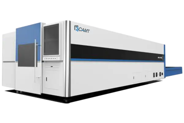
The fiber laser cutting machine range covers three architectures. The enclosed ULE with twin exchange tables matters here for a reason that is not about cut quality in the abstract: with two tables, a bead that starts mid-nest is caught before the next pallet is cut, not at de-nesting with forty parts already made. The open-type ULF single-table machine suits mixed work where the operator watches the cut and can stop on the first bad contour.
What we will not claim: that a machine eliminates dross. The bead is an outcome of a process running on a particular sheet on a particular afternoon, and any supplier promising otherwise is selling a specification rather than an edge. Send photographs of both faces with your material, thickness and gas and we will say which term in the ledger the evidence points at.