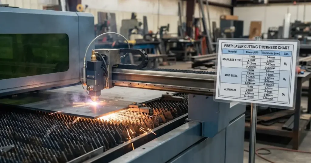
Choosing the right fiber laser cutting machine starts with understanding how much material thickness it can process reliably. A 3kW fiber laser may handle everyday sheet metal jobs efficiently, while a 6kW or 12kW system can offer greater cutting capacity and higher productivity on thicker materials. However, the actual cutting thickness is not determined by laser power alone. For the power rating behind each of those bands, see how much laser power you need.
Material type, assist gas, laser source, cutting head, gas pressure, focus position, and required edge quality all affect the result.
This fiber laser cutting thickness chart by power and material provides a practical reference for comparing 1kW to 12kW fiber laser systems across carbon steel, stainless steel, aluminum, brass, and copper. It also explains the difference between maximum cutting thickness and stable production thickness, helping manufacturers choose equipment based on real manufacturing requirements rather than headline specifications.
1. The chart: power by material
Figures are in millimetres, shown as sever ceiling / repeatable production band. The ceiling is one successful pierce and separation on clean, flat, known-grade sheet; the band is what a properly configured machine holds across a shift at an edge your customer will accept. Mild steel assumes oxygen assist, stainless and aluminium high-pressure nitrogen, brass and copper nitrogen with back-reflection protection in place.
| Source power | Mild steel (O₂) | Stainless (N₂) | Aluminium (N₂) | Brass / copper (N₂) | What caps the row |
|---|---|---|---|---|---|
| 1 kW | 8–10 / 3–5 | 4–5 / 2–3 | 2–3 / 1–2 | 1–2 / ≤1 | Pierce time, taper |
| 2 kW | 12–14 / 6–8 | 6–8 / 4–5 | 4–5 / 2–3 | 2–3 / 1–2 | Nitrogen pressure, melt ejection |
| 3 kW | 16–18 / 8–12 | 8–10 / 5–8 | 5–6 / 3–5 | 3–4 / 2–3 | Gas flow through a narrow kerf |
| 6 kW | 20–25 / 12–16 | 12–16 / 8–12 | 8–12 / 6–8 | 4–6 / 3–4 | Gas delivery, optics |
| 12 kW | 30–40 / 20–25 | 20–30 / 12–20 | 15–20 / 10–15 | 6–10 / 4–6 | Process window, slat life, pierce strategy |
These bands are deliberately conservative: they eliminate obviously wrong configurations. Machines above 12 kW push the upper rows further, but the shape does not change — mild steel ahead of stainless, stainless ahead of aluminium, reflective alloys trailing both.
Suppliers quote ratings the table does not print. Screen them without inventing a number:
| Quoted source power | Screen it against |
|---|---|
| 1.5 kW | the 1 kW row |
| 4 kW | the 3 kW row |
| 8 kW / 10 kW | the 6 kW row |
Read down, not up. If a supplier quotes 4 kW, screen it against the 3 kW row. We leave those cells unfilled deliberately: a figure for an intermediate rating would be an interpolation, not a cut test — and interpolated figures are why published charts disagree in the first place.
Two things follow. A shop cutting the same stainless grade daily should buy against the production band and ask what speed the machine holds there, not against the ceiling. And a shop whose thickest job arrives once a year should price that work outside before letting it set the power band.
2. Which power band fits your shop
| Typical work | Start at | Move up a band when |
|---|---|---|
| Thin mixed sheet, electrical cabinets, decorative panels, small brackets | 1 kW | Small-contour cycle time is set by acceleration and head settling, not the source |
| Mixed orders: enclosures, metal furniture, machinery covers, kitchen equipment | 2 kW | Stainless or aluminium becomes daily work, or oxide removal before coating eats the shift |
| Medium plate: agricultural and construction parts, frames, housings | 3 kW | Peak nitrogen demand outgrows the gas plant, or the mix shifts to thicker stainless |
| High-volume thin and medium sheet, short delivery cycles | 6 kW | Sheet change, not cutting, is the bottleneck — run the arithmetic in section 6 first |
| Heavy structural plate, large components, high output | 12 kW | Only after the occasional thick job has been priced against outside capacity |
| Round, square and rectangular profiles, bevelled joints | A tube laser | Wall thickness is only half the problem; chuck rotation and seam position decide the rest |
There are no thickness figures here. Those live in section 1. Repeating them beside every application is how a reference chart turns into a brochure — and why one power rating arrives with three different numbers in three quotations.
3. Different metals use different laser cutting rules
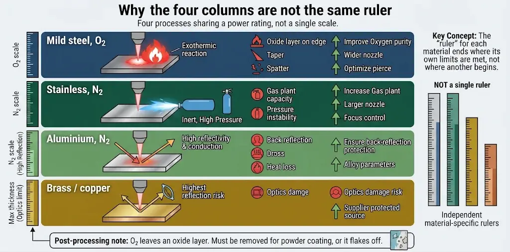
Reading across a row as if four materials shared one scale is the most common misuse of a thickness chart. They are four processes sharing a power rating.
| Column | Where the energy comes from | What the gas does | What stops you first | To move this column up |
|---|---|---|---|---|
| Mild steel, O₂ | Laser plus an exothermic reaction: oxygen burns the steel | Low pressure, drives the oxide melt out | Oxide on the edge, taper, spatter | Oxygen purity, pierce strategy, wider nozzle |
| Stainless, N₂ | The laser alone — nitrogen adds no energy | High pressure clears the melt, keeps the edge oxide-free | Gas plant capacity, pressure stability | Gas plant, nozzle orifice, focus depth, grade parameters |
| Aluminium, N₂ | The laser alone, against reflectivity and conduction | High-pressure melt ejection | Back reflection, dross, heat lost into the sheet | Confirmed back-reflection protection, alloy parameters |
| Brass / copper | The laser alone, highest reflection risk | Same, at lower achievable thickness | Reflected energy reaching the optics | Supplier confirmation that the source is protected |
Compressed air is a third option on thin carbon steel and some stainless work. It can lower gas cost, but edge quality, dross and total cost have to be qualified on your own parts; it is not a drop-in substitute for nitrogen.
Kevin Fradette, writing in The FABRICATOR’s guide to designing parts for laser cutting (2016), notes that with nitrogen “the more power the laser has, the thicker the material that it can process”, then adds the qualifier that matters: “Of course, these are some of the maximum thicknesses possible.” His example is a powder-coated 0.1875 in. steel part — a 3 kW machine may need oxygen for a dross-free edge where a 4 kW machine can deliver it with nitrogen. Same thickness, different gas, different machine.
Oxygen leaves an oxide film. Fradette is blunt about the consequence: if it is not removed before powder coating, the cured finish flakes off because it is bonded to the oxide, not the metal. A mild steel figure is therefore not automatically a finished-part figure. Paint, welding or coating moves the usable thickness down before the laser is considered.
4. Thickness by material: five short answers
The table in section 3 explains the columns. What you actually need per material is what to bring to the cut test:
- Carbon steel. The mill certificate, and the finish requirement if the part is painted or powder-coated — the oxide film decides whether the edge is finished.
- Stainless. A full nest on your grade, not one coupon; pressure has to hold while the whole sheet is cut.
- Aluminium. The exact alloy. Reflectivity changes with alloying elements, and protection must be confirmed for that alloy.
- Brass. Written supplier confirmation for the specific alloy, plus a coupon from the batch.
- Copper. Same confirmation and coupon; for busbars, accuracy matters more than the thickest cut.
Reflective alloys deserve their own line, not a footnote borrowed from aluminium. TWI’s technical note on laser cutting aluminium explains that aluminium is more reflective than carbon-manganese steel or stainless, that reflection comes from the molten pool as well as the sheet, and that alloying elements reduce reflectivity — so pure aluminium is harder to process than a 5000-series alloy.
The “aluminium cutting system” on modern machines is, in TWI’s words, a back-reflection protection system that stops the laser before reflected radiation damages it. TWI’s advice is explicit: “Always check with the laser supplier that the system is designed for processing aluminium before attempting to cut it,” and brass may need the same protection.
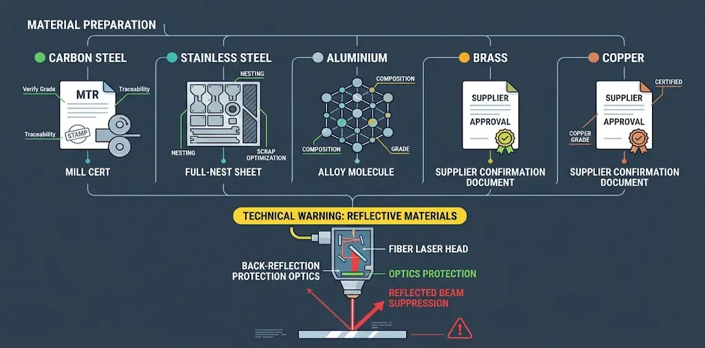
That is a configuration question, not a power question. Adding 3 kW without confirmed back-reflection protection does not make a copper job safe or repeatable, and no chart can tell you whether the protection is fitted. We do not assert compliance for any specific material or machine here; that confirmation has to come from the equipment supplier in writing, against the alloy you intend to run.
Four cases also sit outside most charts:
- Galvanised, coated or filmed sheet needs parameters developed on the coated product.
- High-strength and wear plate needs a coupon from the actual batch before any chart figure is usable.
- Plate beyond roughly 25 mm grows pierce time, taper and dross faster than the useful window; compare plasma, oxyfuel or waterjet on total cost.
- Tube and structural profiles depend on chuck rotation and seam position; a flat-sheet chart does not transfer.
5. Maximum thickness vs production thickness
Maximum cutting thickness is the greatest thickness a machine can cut through once, under one specific set of conditions. Stable production thickness is the range it can process repeatedly while holding speed, edge and consistency across a shift.
A supplier may advertise a 6 kW machine severing 30 mm carbon steel. That says nothing about running 12 mm every day at a speed that meets the target, with low dross and no secondary grinding. The first is a demonstration; the second is a process. Section 1 prints two numbers per cell precisely because one number cannot carry both meanings.
Ask for both in writing, for each material you run, with the gas, nozzle, focus and edge criterion that produced each.
6. What the chart does not print: speed and gas cost
Here is the part no thickness chart prints, and the part that decides whether a bigger source pays for itself.
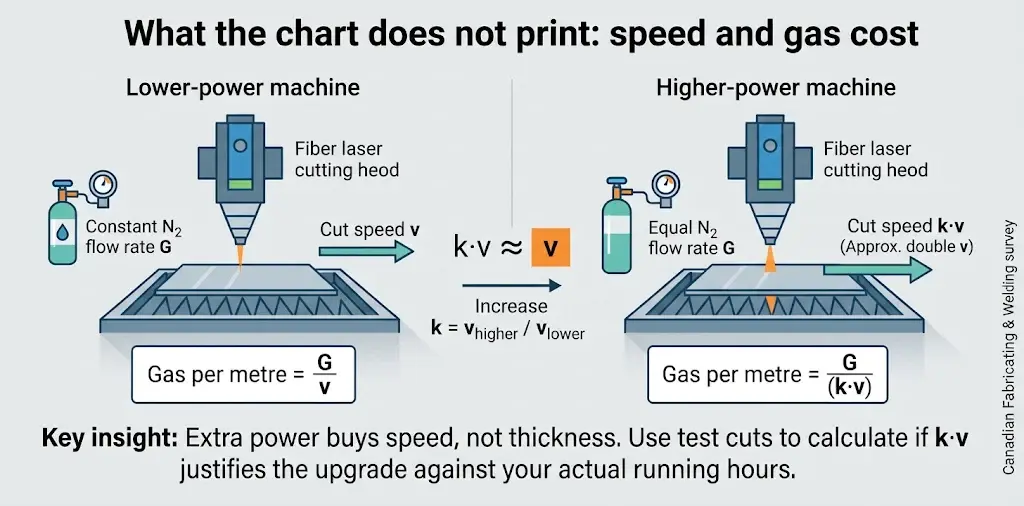
In a 2017 survey of nitrogen use, Rob Colman reported in Canadian Fabricating & Welding that “the nitrogen flow rate generally remains the same regardless of the power of the machine”, quoting Bystronic’s John Kemp: “A 10 kW has a cutting speed of roughly double that of a 6 kW … yet in both cases, the nitrogen consumption is basically equal, so your nitrogen consumption per part goes down when using the 10 kW.”
The article also records machines in the 8 to 10 kW class cutting 1 in. mild steel and up to 1.180 in. stainless or aluminium — 2017 figures from named suppliers, illustrative of the relationship rather than current limits.
The relationship gives you arithmetic you can run on your own quotes:
gas cost per metre of cut = gas cost per laser-on hour ÷ cutting speed at that thickness
Ask two suppliers to quote the same job — say 6 mm 304 stainless on nitrogen — at two power levels, each stating cutting speed on your grade, pierce time, nozzle, pressure and gas per laser-on hour. Call the speed ratio between quotes k. If gas flow is essentially unchanged, gas per metre falls to 1/k on the faster machine, while the thickness ceiling barely moves. That is what extra power buys: a speed column, not a thickness column. The gas choice that changes those figures is covered in laser cutting assist gas.
| Line to put in the quote | Lower-power | Higher-power | Why it matters |
|---|---|---|---|
| Cut speed on your 6 mm 304, N₂ | v | k·v | Cut test on your material |
| N₂ per laser-on hour | G | ≈ G | Gas meter or supply contract |
| Gas per metre of cut | G/v | G/(k·v) | Calculated, not quoted |
| Pierce time per contour | measure | measure | The program, not the brochure |
| Thickness ceiling in the chart | printed | printed | Almost unchanged |
| Other costs to price | Price, power, cooling, gas plant, optics, maintenance, labour, finishing | Same, plus idle capacity | Whether k is large enough to matter |
None of v, k or G should arrive as a generic vendor number; they come from the test cut on your plate. What you are testing is whether k is large enough, on the hours you actually run, to justify the upgrade. A chart without a cutting-speed column cannot answer that at all.
Power selection against your hour distribution is a separate exercise, and How to Choose a Fiber Laser Cutting Machine works through it; do not squeeze that decision out of a thickness chart.
7. The six assumptions behind any number
A published figure is one machine, one plate, one parameter set, one day. Tim Heston’s 2023 account of how Cupples’ J&J Co. holds a laser-cut edge inventories what a chart leaves out: mill and batch, carbon content, surface scale, flatness, standoff, nozzle orifice, laminar gas flow, and focus position that changes with grade and thickness.
| The chart assumes | What may be true on your floor | How to check | Direction |
|---|---|---|---|
| A consistent grade | A36 from one mill cuts differently from another | Mill certificate; coupon from each batch | Down, unpredictably |
| Clean, flat sheet | Scale, oil or bow changes standoff and pierce | Measure standoff across the sheet | Down, random dross |
| Stable gas pressure | Two heads drawing at once drop line pressure | Log nozzle pressure during a full nest | Down mid-shift |
| Correct nozzle and focus | A worn or off-centre nozzle creates turbulence | Inspect orifice and centring | Down, with taper |
| Clean delivery optics | A contaminated window absorbs power first | Check the window daily | Down, then suddenly |
| A developed parameter library | A generic controller table is not tuned to your alloy | Ask which grade, gas and nozzle it was built on | Down, or inconsistent |
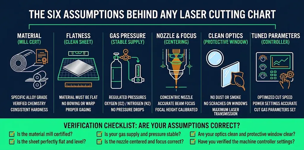
Heston describes a shop running the head for hours in a zigzag across one sheet, testing thicknesses without leaving the material, because a cut that “goes bad” after cutting well points to gas flow, not to a wrong figure. Read a chart the same way: a claim that holds only while the whole chain holds. Consumables are part of that chain — nozzles, ceramic holders and protective windows are working parts, listed under spare parts and consumables.
Six questions for whoever supplied the table. Write the answers next to the row they apply to:
- Which gas, what purity, what nozzle pressure — and does it hold when a second head draws?
- Was success separation only, or an edge criterion such as ISO 9013 perpendicularity and roughness?
- One coupon, or a full nest long enough for pressure and optics temperature to settle?
- Which grade, which mill, what surface condition — stretcher-levelled or as-rolled?
- Which nozzle diameter, focus and standoff, and where are they stored in the controller?
- What was the pierce time, and is it inside the cycle time you were quoted?
If those answers need turning into a repeatable setup routine, that belongs with technical support and operator training, not a spreadsheet someone keeps in their head.
8. Turn the chart into a decision: four steps
Step 1 — List materials and hours, not the thickest job. Split the work into three buckets. The bucket holding your laser-on hours sets the configuration; the rare job is a utilisation question, not a capability gap.
| Thickness bucket | Production importance | What it decides |
|---|---|---|
| Regular work, every day | Most laser-on hours | Machine configuration and gas plant |
| Occasional thick plates | Periodic, schedulable | Whether to carry reserve capacity |
| Maximum requested thickness | Rare or special orders | Validate, outsource or decline |
Step 2 — Read section 1 backwards from your part mix. The column that matters is the one you spend hours in.
| If most hours are | Read this column | Verify before going up a band |
|---|---|---|
| 0.5–3 mm mixed sheet, many small contours | All columns, thin end | Acceleration and head settling; power is rarely the limit |
| 4–10 mm mild steel, oxygen | Mild steel (O₂) | Oxide removal before paint or powder coat |
| 4–10 mm stainless, oxide-free edge | Stainless (N₂) | Gas plant capacity across a full nest |
| Regular aluminium or brass | Aluminium / brass | Written back-reflection confirmation for that alloy |
| Occasional plate above 20 mm | Mild steel (O₂), or another process | Pierce time, taper, dross, idle capacity |
Step 3 — Run the section 6 arithmetic on two real quotes. Compare speed on your grade, gas per laser-on hour and pierce time, then put the upgrade beside power, cooling, gas plant, consumables, maintenance, labour and finishing. Price occasional thick work outside before it moves you up a band.
Step 4 — Make the cut test your specification. Bring your own stock, run the daily thickness and the thickest accepted job on one nest, and have speed, gas pressure, nozzle, focus and pierce time recorded against each. That record is what you sign against.
9. Where CAMT fits
We will not claim any figure in section 1 as a CAMT specification. The figures worth signing against are the ones produced on your material, with your gas, on the machine you are buying. What we can do is narrow the configuration first.
ULF open-type single-table cutter
The ULF open-type machine is listed at 1–6 kW on its own specification table, with an open structure for hand-loaded, mixed work. It suits small and medium shops running custom orders and short batches.
ULE enclosed exchange-table machine
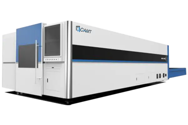
The ULE enclosed exchange-table machine fits shops where sheet changes dominate: twin pallets let the next sheet be prepared while the current one is cut, and the enclosure contains fumes, sparks and dust. Its own specification table lists 6–12 kW and an automatic twin exchange table.
Two CAMT pages quote this machine differently, and it is worth saying plainly: our laser cutting machine range overview lists 1–12 kW+ for the ULE, while the ULE specification table lists 6–12 kW. The model’s own spec sheet governs a quotation; the overview summarises the product family, and its working-area list differs for the same reason. Ask for the configuration sheet of the exact model quoted.
The same caution applies to materials. The overview lists copper; the ULF, ULE and ULT model pages list titanium but not copper. Confirm the alloy against the model you are buying, in writing, before it enters a schedule.
ULT pipe and tube laser
The ULT pipe and tube laser handles round, square and rectangular profiles, with plate-and-tube capability on selected configurations. The range overview adds tube diameters of φ15–220 mm, lengths of 6000–8000 mm, 3D bevel cutting, automatic chuck rotation and optional automatic loading; its model specification table lists 1–6 kW. For furniture, fitness equipment and structural work, seam position, chuck rotation and bevel geometry decide the result — not a flat-sheet chart.
Cutting and bending usually happen in the same shop, so the edge the laser leaves is the edge the press brake has to form; oxide, dross and taper become downstream problems. Holding the production band over time is the work covered by maintenance and upgrades.
Send your material list, thicknesses with the hours spent on each, sheet formats and edge requirements through the contact page. We will come back with a configuration and the reasoning — including the case where a smaller machine, or no new machine, is the right answer.
10. FAQ
Can a 3kW fiber laser cut 20mm steel?
Separation is not production. A cut near the top of a band is slow, parameter-sensitive and usually leaves an oxide edge needing work before coating. If that thickness is regular work, ask for a cycle-time run on your own program and compare it with the next band using section 6.
Can a 6kW fiber laser cut 25mm carbon steel?
The better question is what speed and edge it holds there, and whether one annual job justifies carrying that capacity. Get the recommended continuous production thickness alongside the maximum, with the gas, nozzle and focus that produced both. Section 5 explains why the two are not interchangeable.
What is the difference between oxygen and nitrogen laser cutting?
Oxygen adds exothermic heat and leaves an oxide film; nitrogen adds no energy and ejects the melt at high pressure for a clean edge. That is why the mild steel and stainless columns in section 1 are different rulers. Compressed air can lower gas cost on thin work, but needs qualifying on your parts.
Why does my 6kW machine struggle at a thickness the chart says it can cut?
Work down the six assumptions in section 7 before blaming the source. Pressure under load, a worn nozzle, focus set for another thickness, plate scale, a contaminated window and a library built for a different grade all look the same. One pierce proves a ceiling, not a shift.
Can I use the mild steel column for stainless or aluminium?
No. Oxygen adds energy; nitrogen contributes none and ejects melt at high pressure. Reflective alloys add a back-reflection constraint. The columns move with different variables, so a ratio from one cannot be applied to another.
What about copper, brass and galvanised sheet?
Treat each as a separate qualification. TWI notes that brass may need back-reflection protection and advises checking with the laser supplier before any new material. Coated sheet needs parameters developed on the coated product. Get each confirmed in writing for the exact alloy or coating, then cut a coupon.