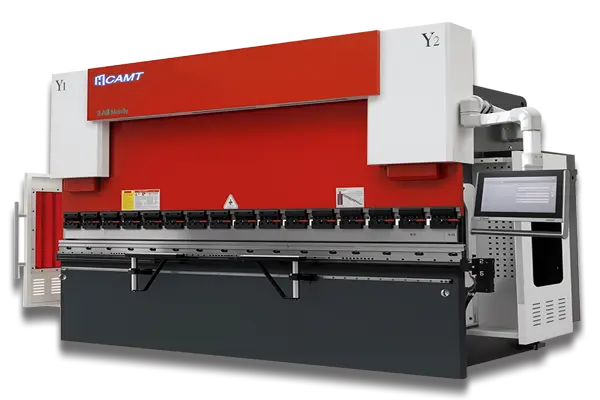
When selecting press brake tooling, checking the machine’s total tonnage is not enough. Every punch, die, and supporting component has its own load limit, often specified in tons per meter (t/m). If the bending force exceeds this rating, the tooling may deform, crack, or fracture—even when the press brake itself is operating below its rated capacity.
Understanding tons per meter helps you determine how much force a tooling setup can safely withstand over the actual bending length. This guide explains how tooling load ratings work, how to calculate the maximum allowable tonnage, and how to avoid dangerous overloads when bending thick plates, high-strength materials, or short workpieces.

What Does Tons per Meter Mean in Press Brake Tooling?
Tons per meter (t/m) is the maximum allowable bending force distributed along one meter of press brake tooling. If a punch is rated at 80 t/m, one meter of that punch can withstand a maximum distributed load of 80 tons — but if the actual bending length is only 500 mm, the allowable total load is reduced accordingly. Tooling load ratings must therefore always be considered together with the actual length of the workpiece being bent.
Ratings appear in three units, and mixing them is one of the most common ways load checks go wrong:
| Metric tons per meter | kN/m | US tons per foot |
|---|---|---|
| 50 t/m | 490 kN/m | 16.8 t/ft |
| 100 t/m | 981 kN/m | 33.6 t/ft |
| 200 t/m | 1,961 kN/m | 67.2 t/ft |
One metric tonne equals 1.102 US short tons and 9.81 kN; one meter equals 3.281 feet. Ratings around 100 t/m are commonly cited for standard European-style precision tooling, while heavy-duty and special profiles run considerably higher — but the number that matters is the one published for the specific tool in your hand, not a category average.
A related distinction matters when reading documentation. A per-meter rating describes capacity along the tool’s length — the natural language for tooling that can be sectioned to any length. An absolute load limit describes the total force at which the complete tool fails; the two must never be used interchangeably.
Why Is Tooling Load Capacity Important?

Exceeding the rated load can cause several problems:
- Punch fracture: cracks or sudden breakage, particularly around narrow punch tips or reduced cross-sections.
- Die shoulder damage: deformation or fracture of the shoulders surrounding the V-opening.
- Permanent deformation: dimensional changes that affect bending accuracy and repeatability.
- Clamping system damage: additional stress on the punch holder and clamping components.
- Operator safety risks: a fractured punch or die can release metal fragments at high speed.
The failure mode depends on the tool. Overloading a soft, planed-style tool tends to be loud but survivable: the section bends or snaps with a bang and pieces drop to the floor. Early precision-ground tools told a different story — through-hardened to very high hardness, they were extremely brittle and prone to throwing shrapnel. In one published account, a fragment from an exploded precision-ground die flew more than 80 ft, struck a cinderblock wall, and dented it (Canadian Metalworking).
Because a violently failing tool is a point-of-operation hazard like any other, the load check has a safety tail. OSHA’s machine guarding guidance for press brakes requires general machine guards to protect the operator and others in the machine area from point-of-operation hazards (OSHA eTool). Safeguarding does not replace the load check; it protects people from the failure the load check was supposed to prevent. Our safety arrangements page covers how we configure guarding on the machines we build (CAMT).
The distinction running through all of these failure modes: machine capacity and tooling capacity are separate limits. A press brake may have sufficient hydraulic force to complete a bend, but its installed tooling may not be rated to withstand that force.
How to Calculate the Maximum Allowable Tooling Load
The maximum allowable load depends on two factors — the tooling’s rated load per meter and the actual length over which the bending force is applied:
Maximum Allowable Tooling Load = Tooling Load Rating × Actual Loaded Length
Example 1: A Standard Bend
Punch rated 80 t/m, die rated 100 t/m, bending length 1.5 m:
- Punch: 80 × 1.5 = 120 tons
- Die: 100 × 1.5 = 150 tons
The punch has the lower rating, so the maximum allowable tooling load = 120 tons, subject to the manufacturer’s specified loading conditions. Even though the die can withstand 150 tons, the setup must not exceed the punch’s limit.

Example 2: A Short Workpiece
Same tooling, bending length 500 mm (0.5 m):
- Punch: 80 × 0.5 = 40 tons
- Die: 100 × 0.5 = 50 tons
Maximum allowable tooling load = 40 tons. A tooling set rated for 80 t/m cannot automatically withstand 80 tons on a 500 mm workpiece — the shorter the loaded length, the lower the permitted total force.
Note that this calculation is valid only when the manufacturer’s rating applies to the stated loaded length; some tooling systems carry additional minimum-length, concentrated-load, or sectional-tool restrictions that must be checked separately.
Where do the ratings come from? Precision-ground tooling normally carries its per-meter figure etched on the tool or listed in the catalog next to the profile number, generally valid for a uniformly distributed load over complete, fully supported segments. A gooseneck punch drops into the same holder as a straight punch but carries a fraction of the load, so never infer a tool’s rating from the tool that usually sits next to it. If you cannot find the number for the exact profile, segment length and interface you are running, ask the tooling supplier for written documentation. For older planed-style tooling that was never rated, Section 6 gives a published screening method.
How to Calculate Tons per Meter for an Actual Bending Job
The other side of the safety check is determining how much force a bending operation actually requires:
Required Load per Meter = Required Bending Force ÷ Actual Bending Length
For example, a job requiring an estimated 36 metric tons over a 600 mm workpiece works out to 36 ÷ 0.6 = 60 t/m. If the punch is rated at 80 t/m and the die at 100 t/m, the average line load is below both ratings — but this does not automatically approve the setup. Concentrated-load limits, tool support conditions, minimum working length, and any tooling-manufacturer restrictions must also be satisfied.
What Factors Affect the Required Bending Load?
| Factor | Effect on Bending Force |
|---|---|
| Material thickness | Increasing thickness significantly increases the required force. |
| Material tensile strength | Higher-strength materials generally require more bending force. |
| V-die opening | A wider V-opening generally reduces the required bending force. |
| Bending length | Longer bending lines require greater total force. |
| Bending method | Air bending, bottoming, and coining have different force requirements. |
| Punch and die geometry | Tool radius, profile, and contact conditions influence the forming process. |
Timing matters as well: forming force does not build evenly through the stroke. Published analysis of the air-bending curve shows that roughly 80 percent of the total tonnage is developed within the first 20 degrees of bend angle (The FABRICATOR) — so even a shallow first hit can put serious pressure on marginal tooling. Bending 6 mm stainless steel, for instance, requires more force than 6 mm mild steel under comparable conditions, and a tighter V-opening raises the demand further.
Always calculate the actual demand using a suitable tonnage chart for the material and method. Do not treat a tooling load rating as a bending-force calculator.
Machine Tonnage vs Tooling Load Limits: The Full Load Chain
One of the most common mistakes is assuming the machine’s rated tonnage determines the maximum safe load for every tooling configuration. In reality, each component in the load path serves and protects something different:
| Parameter | What It Defines | What It Protects |
|---|---|---|
| Machine rated tonnage | Maximum rated pressing force under specified conditions | Press brake structure and drive system |
| Centerline load limit | Maximum force per unit length the ram and bed can take without permanent deflection | Ram and bed straightness |
| Sinking limit | Load the ram and bed surfaces can take before the tool embeds | Ram and bed surfaces |
| Punch load rating | Maximum allowable load on the punch | Upper tooling |
| Die load rating | Maximum allowable load on the lower die | Lower tooling |
| Clamping system rating | Permitted load and clamping conditions | Tool retention and mounting components |
| Adapter or holder rating | Allowable load for the supporting component | Tooling support structure |
The lowest applicable rating in the load path governs. Consider a 200-ton press brake fitted with an 80 t/m punch, a 100 t/m die, and a 70 t/m adapter: the adapter has the lowest line-load rating, so the usable load cannot exceed its limit even if the punch, die, and press brake have higher capacities.
The machine’s total tonnage must also be checked independently — the two machine-side limits below put their own ceiling on what any tool can legitimately carry.
The Centerline Load Limit and the 60 Percent Rule
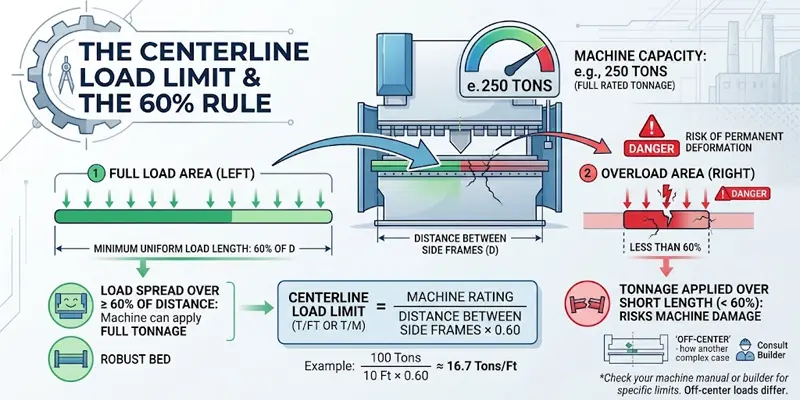
A press brake is designed to take its full rated tonnage only when the load is spread over at least about 60 percent of the distance between the side frames. Pressing full tonnage over a shorter length risks permanent deformation of the bed and ram.
The published rule of thumb: a 250-ton press with 14 ft between the side frames can apply full load over a minimum of 0.60 × 14 = 8.4 ft, which works out to 250 ÷ 8.4 ≈ 30 US tons per foot (The FABRICATOR). The same relationship is formalized as a centerline load limit — machine rating ÷ (distance between side frames × 0.60); a 100-ton machine with 10 ft between side frames works out to about 16.7 t/ft (The FABRICATOR).
The limit is machine-specific, so ask the builder for it in writing for your specific make and model. Off-center work changes the picture again — the available tonnage and local limits differ, and that is another question for the builder. Choosing the machine itself is its own selection exercise, covered in our press brake tonnage guide for machine selection.
The Sinking Limit
With short or heavily loaded tools, the contact area between the tool shoulders and the ram or bed can itself become the weak point — the tool gradually embeds itself into the machine surface.
A published estimating method multiplies the shoulder contact area by the allowable pressure of the ram surface — on the order of 15 US tons per square foot — and applies a 20 percent safety reduction. For tools with 0.350 in shoulders (The FABRICATOR):
Land area = (0.350 × 2) × 12 = 8.4 sq. in. Total tons = 8.4 × 15 = 126 Sinking limit = 126 × 0.80 = 100.8 t/ft
That is comfortably high for a long tool, but reachable by a short, wide-shouldered setup under concentrated load. Larger shoulders spread the same force over more area, which is one reason heavier tool sections earn their keep on thick work.
Why Short Bends and Concentrated Loads Are Dangerous
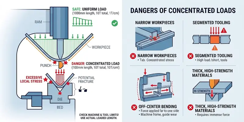
When a narrow workpiece is bent using only a short section of tooling, the force concentrates into a smaller area, creating excessive local stress even when the total bending force appears low. Four situations cause this:
1. Narrow workpieces. A small tab may require high force because of its thickness and material strength; the short bending length concentrates that force into a limited section of tooling.
2. Segmented tooling. Check the load rating and minimum working length of each individual segment — and as Section 6 shows, short segments should be run at substantially reduced load. Installing additional sections does not automatically distribute the force if the workpiece only loads a small portion of the setup.
3. Off-center bending. Bending near one end of the machine produces uneven loading across the ram, frame, guides, and bed; the load position may exceed the manufacturer’s permitted limits even when total force is below rated tonnage.
4. Thick, high-strength materials. High-strength steel and stainless require significantly higher forces; combined with a short bending length or narrow V-opening, the overload risk multiplies.
Before starting a short or heavy bending operation: check the machine manufacturer’s concentrated-load limits, confirm the punch and die are approved for the material and method, use the actual loaded length rather than the full installed tooling length, verify segmented tooling is correctly seated and supported, and follow the builder’s off-center restrictions. Never assume that reducing the total bending force makes a short bend safe — local loading restrictions still apply.
Built-In Derating and Unrated Tooling
Goosenecks, Acute Dies and Short Segments
Nothing derates a load limit faster than removing material from the tool’s load path. A gooseneck’s throat cut removes cross-section right where the force flows. Published rule-of-thumb figures for conventional tooling show how sharply capacity falls as the throat deepens (The FABRICATOR):
| Tool geometry | Relative capacity | Rule-of-thumb limit, US t/ft |
|---|---|---|
| Straight punch (no throat) | 100% | 30 |
| 70% throat depth | 70% | 21 |
| 75% throat depth | 50% | 15 |
| 80% throat depth | 30% | 9 |
| 85% throat depth | 20% | 6 |
Matching die figures: a standard V-die around 30 t/ft under maximum load, acute tooling halved to roughly 15 t/ft or less to avoid splitting the die, and sectionalized tooling halved as well to prevent spot damage when the load lands on a short segment. These are illustrative values for conventional geometries — the rating published for your actual punch governs, and a deep gooseneck can fall well below the table. Check the derating before the tool is on the bed, because the fix usually means opening the die, changing the method or re-sequencing the bends — decisions that belong in engineering, not at the machine.
Estimating the Limit of an Unrated Punch
Plenty of tooling in service — particularly older American planed-style tooling — carries no rating at all. If supplier documentation is unavailable, a published screening method estimates a punch’s load limit from its neck geometry. Three measurements are needed, all in millimeters:
- l — distance from the tool nose to the tangent point between the neck and the inside radius,
- T — width of the neck at that same point,
- b — length of the tool.
With a safety coefficient δ = 19.98 (The FABRICATOR):
Z = (b × T²) / 6 → P₁ = (δ × Z) / l → P = √(2 × P₁)
where P is the punch’s resistance to pressure in tons per square meter. Worked with representative dimensions — l = 38.1 mm, T = 15.87 mm, b = 1,000 mm — the sequence runs:
- Z = (1,000 × 15.87²) / 6 ≈ 41,976
- P₁ = (19.98 × 41,976) / 38.1 ≈ 22,013
- P = √(2 × 22,013) ≈ 209 t/m
Treat that 209 as what it is: a screening estimate. The full picture involves tool material, heat treatment and hardness, which the simplified formula folds into a single coefficient. Use the estimate to flag risky setups, and confirm any setup near the limit with the tooling manufacturer before running production.
How to Prevent Press Brake Tooling Overload
1. Select the Correct V-Die Opening
A narrower V-opening requires more force; a wider opening reduces it. A common starting guideline for air bending mild steel is a V-opening of approximately 8 times the material thickness, adjusted for the material, desired inside radius, and bend geometry. For thick or high-strength materials, a larger V-opening may help reduce excessive loads. Read our guide to press brake tooling selection for how punch profiles and tooling geometry affect performance, and our guide to choosing a V-die opening for the selection workflow in detail.
2. Inspect Tooling Before Production
Tooling with cracks, chips, deformation, or excessive wear should not be used for high-load bending. Pay particular attention to punch tips and narrow neck sections, die shoulders, contact and seating surfaces, clamping interfaces, and section joints in segmented tooling. If damage is suspected, remove the tooling from service and have it inspected by qualified personnel.

3. Check the Clamping System
Incorrect installation, poor seating, or unsuitable clamping components can lead to punch movement and uneven loading. For demanding applications, an appropriately specified hydraulic or mechanical clamping system improves tool retention and setup consistency. Explore CAMT press brake tooling clamping systems for manual, hydraulic, and pneumatic options.
4. Maintain a Suitable Operating Margin
Do not plan production around operating at the exact rated limit. Material properties vary between batches, so use realistic upper-bound values when calculating the required force, and apply any capacity margin required by the machine and tooling manufacturers — there is no single reserve percentage for every system. Where a check shows demand creeping toward a rating, the standard remedies run in this order: pick a larger die opening and recalculate, change the forming method, or move to a tool section with a higher rating (Canadian Metalworking).
Choosing Tooling and Machine Configuration for High-Tonnage Work
Selecting tooling based only on shape or dimensions is insufficient for thick plates, high-strength materials, or demanding schedules:
| Selection Factor | What to Check |
|---|---|
| Load rating | Maximum allowable force per meter or per segment |
| Tool material | Strength, toughness, and resistance to deformation |
| Tool geometry | Punch profile, tip radius, die opening, shoulder design, and — for clearance work — throat depth derating (see the gooseneck table above) |
| Tool length | Actual working length and minimum permitted loading length |
| Compatibility | Machine interface, clamping standard, and holder dimensions |
| Production conditions | Material strength, thickness, bending method, and cycle frequency |
For high-tonnage applications, tooling should be selected as part of the complete machine configuration rather than as an independent accessory. CAMT supplies CNC press brakes in standard synchronous, multi-axis CNC, tandem, and heavy-duty configurations. Explore CAMT CNC press brake solutions to compare available configurations.
If you are purchasing a new press brake or upgrading an existing machine, review tooling capacity before finalizing the configuration — a machine with high nominal tonnage may not suit your production if its tooling interface or permitted load distribution does not match. Before purchasing, consider:
- What is the maximum material thickness and tensile strength you need to bend?
- What is your maximum and minimum bending length?
- Will you regularly bend short, narrow workpieces?
- Do you need standard or heavy-duty punch and die configurations?
- What tooling standard does your workshop use? Shops standardizing on the New Standard / WILA-style interface can review the system on our WILA smart tooling page.
- Are hydraulic or quick-change clamping systems required?
- Does the machine support your planned off-center and concentrated-load applications?
- Are the required adapters and tooling holders rated for the expected load?
Additional features such as CNC crowning and tooling management systems can improve process consistency in high-volume production. CAMT crowning systems compensate for machine deflection during bending — but crowning is an angle-consistency solution, not a substitute for checking load limits. CAMT tooling and storage solutions help organize and handle heavy-duty tooling efficiently during setup and changeover.
Frequently Asked Questions About Press Brake Tooling Load Limits
What does 100 tons per meter mean on a press brake punch?
The punch has a rated maximum distributed load of 100 tons over one meter of working length. For a 500 mm loaded length, the theoretical allowable total load would be 50 tons, with additional minimum-length and concentrated-load restrictions possibly applying.
Can I use a 100-ton punch on a 200-ton press brake?
Not automatically. The punch must be rated for the actual bending load and working length; if its permitted load is lower than the required force, the setup is unsuitable regardless of machine capacity.
Doesn't the machine's overload protection protect the tooling?
No. Overload protection watches total force against the machine’s rating. A short, concentrated bend can exceed the tool’s per-meter limit at a small fraction of machine capacity, and the machine will report nothing wrong.
Does bottoming or coining change a tool's load limit?
The limit itself is fixed — it belongs to the tool’s cross-section. What changes is the demand: bottoming and coining require substantially higher force than air bending, so a setup comfortably inside the rating in air bending can cross the line when the method changes.
Can I use segmented tooling for high-tonnage bending?
Yes, provided it is specifically rated for the intended application. Check the load rating of each relevant section, minimum working length, support conditions, and clamping compatibility — do not assume the combined installed length determines the allowable load.
How can I tell whether my existing tooling is suitable for a new machine?
Check the tooling profile, rated load, clamping interface, holder dimensions, and tool height, and verify that every supporting component can accommodate the expected load and its distribution. If documentation is incomplete, contact the tooling manufacturer before using it.
Final Thoughts
A setup is safe only when it sits below every applicable limit: the job’s required line load against the tooling ratings, the load-path minimum set by the weakest component, and the machine’s centerline and sinking limits. The checks that confirm this take minutes, not hours — and they belong in the setup sheet, not in memory.
If you are planning to purchase a new press brake, upgrade your tooling system, or handle thicker and higher-strength materials, the right combination of machine capacity, tooling, and clamping configuration prevents unnecessary downtime and costly tooling damage.
Need help selecting a press brake or matching tooling to your production requirements? Contact CAMT’s engineering team with your material type, thickness, bending length, and required tooling configuration.