A flange that is too short can turn an otherwise straightforward press brake operation into a difficult production problem. The sheet may lose proper support on the V-die shoulders, slip into the die opening, or produce inconsistent bends. For manufacturers, this can mean rejected parts, repeated setup adjustments, and unnecessary tooling costs.
The good news is that minimum flange length can be estimated before any metal is cut. For a 90-degree bend in a standard V-die, the working estimate is roughly 0.7 times the V-die opening, with a more conservative guideline of 0.77 × V used across much of the tooling industry. This guide explains where those numbers come from, how the bend angle changes them, how to check real tooling limitations, and what to do when a part’s flange is shorter than the recommended minimum.

1. What Is Minimum Flange Length in Press Brake Bending?
Minimum flange length is the shortest flange dimension that can be formed reliably using a particular press brake tooling setup.
During conventional air bending, the sheet rests on two shoulders of the V-shaped lower die. As the punch moves downward, the material bends into the opening while the surrounding sheet remains supported by the die shoulders. The flange must extend far enough to maintain stable contact with the tooling throughout the bending operation.
When the flange is too short, several problems can occur:
- Loss of die shoulder support: the sheet edge slips into the V-opening instead of remaining supported.
- Inconsistent bend angles: unstable material positioning produces dimensional variation between parts.
- Poor positioning: a short leg offers too little contact area for reliable backgauge location.
- Part deformation and scrap: the flange may tilt or distort, forcing repeated adjustments or rework.
It is important to understand that minimum flange length is not simply a function of sheet thickness. The actual V-die opening and tooling geometry are the critical factors — thickness enters the picture indirectly, through the opening it leads you to select.
2. Minimum Flange Length Formula

For conventional 90-degree air bending with a standard V-die, a commonly used preliminary calculation is:
Lmin ≈ 0.7 × V
Where:
- Lmin = estimated minimum flange length.
- V = actual V-die opening width.
The makeup of that factor explains where it comes from. Half the opening — 0.5 × V — is the shortest a flange can be and still reach the center of the gap; a leg of exactly that length is balanced on the brink and tips into the void the moment the punch descends. The rest of the factor is bearing: press brake columnist Steve Benson puts the working contact on the die shoulder at 20 percent of the die opening, which brings the total to roughly 0.7 × V.
For more conservative preliminary design checks, a factor of approximately 0.77 is also used:
Lmin ≈ 0.77 × V
Paul LeTang, press brake tooling product manager at Bystronic, gives the minimum flange as approximately 77 percent of the die opening — a 1-in. die needs a 0.77-in. flange. The gap between the two factors is not a contradiction; it reflects different shoulder geometries and the amount of safety margin each author builds in. These are empirical tooling guidelines, not universal manufacturing standards. The actual minimum depends on die shoulder geometry, material behavior, bending angle, and the dimension convention used by the tooling manufacturer.
Worked Example: Calculating Minimum Flange Length
Suppose a sheet metal component requires a 90-degree bend, and the selected lower die has a 16 mm V-opening.
- Using the 0.7 factor: 0.7 × 16 = 11.2 mm
- Using the more conservative 0.77 factor: 0.77 × 16 = 12.32 mm
| Calculation basis | Result | Factor |
|---|---|---|
| Initial estimate | 11.2 mm | 0.7 × V |
| Conservative estimate | 12.32 mm | 0.77 × V |
For preliminary part design, approximately 12.5 mm is a more cautious starting target for this example. Actual production suitability still requires tooling verification.
This distinction matters when designing components with tight dimensional requirements. A flange measuring 11 mm might appear acceptable under the 0.7 estimate, but it falls below the more conservative 0.77 guideline — and it lives too close to the minimum to survive normal setup variation.
Minimum Flange Length Reference Table
| V-die opening | 0.7 × V | 0.77 × V |
|---|---|---|
| 6 mm | 4.2 mm | 4.62 mm |
| 8 mm | 5.6 mm | 6.16 mm |
| 10 mm | 7.0 mm | 7.70 mm |
| 12 mm | 8.4 mm | 9.24 mm |
| 16 mm | 11.2 mm | 12.32 mm |
| 20 mm | 14.0 mm | 15.40 mm |
| 25 mm | 17.5 mm | 19.25 mm |
| 32 mm | 22.4 mm | 24.64 mm |
| 40 mm | 28.0 mm | 30.80 mm |
| 50 mm | 35.0 mm | 38.50 mm |
| 60 mm | 42.0 mm | 46.20 mm |
These values are preliminary estimates for conventional air bending, not guaranteed limits for every punch-and-die combination. Compare them against the flange using the same measurement convention as the applicable tooling chart (Section 6 covers the measurement bases in detail), and treat the chart published by the maker of the die actually bolted into your brake as the authoritative number for that tool.
3. How Does V-Die Opening Affect Minimum Flange Length?
The V-die opening is the most important single factor when determining whether a flange can be formed successfully. A wider V-die requires a longer flange, because the material must span a larger opening while maintaining adequate support on the die shoulders.
Consider two components bent under the 0.77 guideline:
- Component A uses a 16 mm V-die: 0.77 × 16 = 12.32 mm
- Component B uses a 32 mm V-die: 0.77 × 32 = 24.64 mm
The second component requires approximately twice the flange length under the same preliminary calculation. This is why selecting the correct V-die is essential when manufacturing parts with short flanges — and why the flange check belongs in die selection from the start, not after the tool is on the machine.
Choosing the narrowest available die is not automatically the answer, however. A smaller opening carries trade-offs of its own — Section 5 walks through them and the hard floor below which a narrower die stops being an option. The full die-selection workflow, including radius and load verification, is covered in our guide to choosing a V-die opening, and the broader tooling landscape in our press brake tooling guide.
4. What Factors Influence Minimum Flange Length?
Although the V-die opening provides a convenient starting point, several other factors determine whether a short flange can be formed successfully.
4.1 Material Thickness
Material thickness affects the selection of the V-die opening, which indirectly influences minimum flange length. For conventional air bending in mild steel, the rule-of-8 convention starts from an opening of approximately eight times the material thickness:
V ≈ 8t
For a 2 mm sheet:
- V = 8 × 2 = 16 mm
- Lmin ≈ 0.77 × 16 = 12.32 mm
This gives a derived relationship of Lmin ≈ 6.16t. It is a planning estimate built on two stacked assumptions — an 8t opening and a 0.77V flange guideline — not a universal rule that every flange must be at least 6.16 times the material thickness. A 2 mm sheet does not automatically require a 12 mm flange in every bending situation; change the opening or the factor and the answer changes with it.

4.2 Material Type and Mechanical Properties
Different metals behave differently during bending:
- Mild steel: the reference material for standard air-bending calculations.
- Stainless steel: typically demands greater forming force and exhibits more springback, often pushing the opening selection wider.
- Aluminum: certain alloys are more susceptible to cracking, especially with small inside bend radii.
- High-strength steel: requires careful tooling selection because of its higher forming resistance and springback behavior.
Material properties do not change the geometric 0.7V or 0.77V estimate itself. They change which opening you select — and through it, the flange the part ends up needing.
4.3 Die Shoulder Geometry
The lower die does more than provide an opening for the material. Its shoulder radius, opening profile, and contact surfaces influence how the sheet is supported and how the material moves during bending.
The shoulder radius in particular moves the bearing requirement. A sharp shoulder radius, common in precision-ground tooling, can carry a flange with contact closer to 10 percent of the opening; a large or compound radius spreads the contact further into the opening and may demand more than the baseline — and it tends to mark the surface less. Two dies with identical nominal V-openings can therefore produce different practical minimums, which is why the tooling maker’s chart outranks any universal multiplier when the flange is close to its limit.

4.4 Punch Geometry and Bend Angle
Punch nose radius and punch geometry influence the contact conditions during forming, and the punch angle must never be wider than the die angle — mating a 90° punch with a much narrower die brings the tools into direct contact, a mismatch that can split and even explosively destroy the die.
The bend angle also changes the flange number itself. The 0.7 × V guideline assumes a 90-degree die; it does not survive an acute one. To close a part past 90°, the punch travels substantially deeper into the V, drawing the sheet inward over the shoulders as it descends — a flange calculated for 90° can disappear into the opening before the acute bend closes. The multipliers scale accordingly: for a 30-degree die, the multiplier is 1.5 times greater than that of a 90-degree die, and the requirement keeps rising as the angle narrows — roughly 110 percent of the opening or more for acute dies as a working band.
A standard 90-degree air-bending estimate should therefore never be applied automatically to:
- Acute-angle bending, including pre-bends for hems.
- Bottoming and coining, where fuller die contact changes the support condition entirely.
- Wipe bending, rotary bending, and special offset or return-flange operations.
For these applications, the actual tooling geometry and forming method must be evaluated separately.
4.5 Backgauge Positioning and Part Geometry
A flange can satisfy the theoretical minimum and still be difficult to manufacture if the backgauge cannot position the workpiece reliably. This commonly occurs with very narrow return flanges, asymmetrical components, parts with multiple bending directions, and components with short edges near existing bends. In these situations, the position and geometry of the backgauge fingers become important.
CAMT offers 2-axis, 4-axis, and 6-axis CNC backgauge configurations to accommodate different workpiece geometries and bending sequences. Explore our Press Brake Backgauge System Selection to understand the available configurations.
5. How to Choose the Right V-Die When the Flange Is Too Short
What should you do if the calculated minimum flange length is greater than the dimension specified on your drawing? Suppose a component requires a 10 mm flange, but the selected 16 mm V-die gives a conservative estimated minimum of 12.32 mm. There are three possible routes.
Solution 1: Use a Narrower V-Die
A narrower V-die reduces the required minimum flange under the same preliminary calculation:
| V-die opening | Estimated minimum flange (0.77V) |
|---|---|
| 16 mm | 12.32 mm |
| 12 mm | 9.24 mm |
| 10 mm | 7.70 mm |
| 8 mm | 6.16 mm |
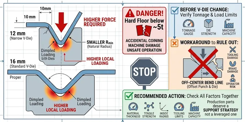
If the required flange is 10 mm, a 12 mm V-die may be worth evaluating. But the narrower opening changes other bending parameters at the same time:
- Higher required bending force.
- Smaller natural inside bend radius.
- Potentially greater risk of material cracking.
- Higher local loading on the die and press brake.
- Different springback and bend-angle behavior.
There is also a hard floor. Chasing a short flange below roughly five times the material thickness invites angular accuracy problems, possible damage to the machine and its tooling, and a genuinely unsafe situation — and the force climb as the opening closes can turn an air-bending setup into an accidental coining operation. Before changing the die, calculate the required tonnage and verify the allowable load of both the tooling and the machine.
Engineering recommendation: never select a narrower V-die based on flange length alone. Check material thickness, tensile strength, minimum inside radius, tooling load limits, and machine capacity together.
One workaround to rule out entirely: shifting the bend line off-center by offsetting the punch and die centers. It occasionally “works” at the bench, but it rarely survives in production and can be dangerous — risking serious damage to the tooling, the brake, and the operator. Production parts deserve a support strategy, not a leveraged one.
Solution 2: Use Special Press Brake Tooling
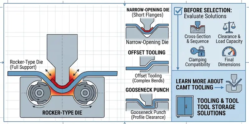
When the part design cannot be changed and a standard V-die cannot produce the required flange, specialized tooling may provide a better solution. Depending on the component geometry, possible options include:
- Narrow-opening dies designed for short-flange applications.
- Custom punches and dies for special profiles.
- Offset tooling for complex return bends (properly engineered, not improvised).
- Gooseneck punches when an existing flange or formed profile creates clearance problems.
- Dedicated hemming or other special forming tools when the operation calls for them.
- Rocker-type dies, whose inserts rotate and support the material throughout the entire bending process — a strong candidate wherever the same short-flange feature repeats across jobs or sits beside cutouts close to the bend line.
The correct solution depends on the actual cross-section and bend sequence. Special tooling should be evaluated for clearance, load capacity, clamping compatibility, and the required final dimensions. CAMT provides standard and customized press brake punches and dies, together with tooling and tool storage solutions. Learn more about CAMT Tooling and Tool Storage Solutions.
Solution 3: Review the Part Design Before Production
Sometimes the most economical solution is to modify the component design rather than introduce special tooling. If the application allows, consider:
- Increasing the flange length slightly.
- Adjusting the adjacent web dimension.
- Changing the bend sequence.
- Modifying the inside bend radius.
- Using a different forming method.
For example, increasing a flange from 10 mm to 13 mm may allow a standard 16 mm V-die to be used instead of purchasing specialized tooling. The final decision should weigh not only whether the part can be bent, but also total production cost, cycle time, dimensional accuracy, and repeatability.
Putting the Three Routes Together: A Worked Scenario
The following scenario shows how the routes interact. Numbers are a narrative example — the decision chain is what transfers.
The part: a bracket in 2 mm 304 stainless. Shortest flange: 8 mm. Two bends: a 90° bend at the mounting tab and a 30° pre-bend that will be flattened into a hem on a later pass. The die rack holds V6, V10, V12 and V16.
The 90° check. For stainless, the opening band starts wider than mild steel, so the first candidate is V12 (6 × t). Screening: 0.7 × 12 = 8.4 mm — the 8 mm flange fails by 0.4 mm. Drop to V10: 0.7 × 10 = 7.0 mm, and the flange clears with a little margin. V10 sits exactly at five times the material thickness, which matters below.
The hem pre-bend. The 30° die changes everything. The multiplier for a 30° included angle is 1.5 × the 90° figure, so the screening value becomes roughly 1.05 × V. On V10 that is about 10.5 mm — the same 8 mm flange that passed the 90° check now fails by 2.5 mm. V6 would bring the acute requirement down to about 6.3 mm, but 6 mm on 2 mm stock is a 3 × t opening, well below the five-times floor from Solution 1.
The verdict. Standard tooling can make the 90° bend and cannot make the hem pre-bend on this flange. The angle, not the thickness, decided the job. The realistic options are the ones above: special tooling built for the support condition (Solution 2), moving the hem to a dedicated hemming tool, or a design conversation (Solution 3). What the numbers forbid is forcing the acute bend with the V10 anyway and hoping the edge stays up.
6. How to Verify Minimum Flange Length Before Production
A calculation is useful during product design, but it should not replace an actual tooling and machine evaluation. Before releasing a part for production, follow these steps.
Step 1: Confirm the drawing dimensions. Identify the exact flange dimension and how it is measured. Check whether the drawing specifies an outside flange dimension, an inside flange dimension, a dimension measured from the bend tangent, or one measured from the theoretical bend intersection. These measurements are not interchangeable — the 0.7V and 0.77V guidelines must be compared using the same measurement convention as the applicable tooling chart. Mixing the bases (checking a flat-pattern number against a formed-part chart value, or the reverse) is a common way short flanges pass review and fail at the brake.
Step 2: Confirm material thickness and type. Measure the actual material thickness rather than relying exclusively on nominal specifications, and identify the grade — especially for stainless steel, aluminum alloys, or high-strength steel.
Step 3: Select the actual punch and die. Confirm the V-die opening, die shoulder radius, punch nose radius, punch angle, tooling height and clamping compatibility, and the maximum allowable tooling load. Do not calculate minimum flange length using an assumed V-opening that differs from the die installed on the machine.
Step 4: Check backgauge contact and clearance. Position the workpiece against the backgauge and check whether the gauge fingers provide stable support, and whether they interfere with the punch, die, or previously formed sections. Two details matter on short-flange work: the stop should leave the flange edge with real bearing on the die shoulder rather than balanced at the brink, and long bends bulge slightly at the ends as they form — a gauge thinner than the material thickness touches only the lower portion of the sheet, so the bulge slides over the finger instead of shoving the whole part off position. For complex parts, simulate the bending sequence where possible and check for collisions before production.
Step 5: Perform a test bend. Use the actual production material and intended tooling, and check whether the flange remains supported during the stroke, whether the material slips or tilts, whether the bend angle is consistent, and whether the finished flange meets drawing tolerances. Keep one caveat in mind: a successful trial bend proves the flange bent once — production reliability lives in the margin between the actual flange and the minimum, not at the minimum itself. If a part runs close to the limit, conduct additional trials before approving the batch, and if angles wander after the flange margin is fixed, the cause usually lies elsewhere — the diagnostic paths are covered in our article on why parts from one batch get different bend angles.
Step 6: Document the approved setup. Record the verified process parameters:
| Parameter | Information to record |
|---|---|
| Material | Grade and material specification |
| Thickness | Actual measured thickness |
| V-die opening | Installed die width |
| Punch | Type, angle, and nose radius |
| Flange length | Drawing and measured dimensions |
| Bend angle | Target and measured result |
| Backgauge | Position and finger arrangement |
| Bending force | Verified operating tonnage |
| Inspection | Approved dimensional results |
Keeping these records makes repeat orders easier to set up and reduces the need for repeated trial bending.
7. How CNC Press Brakes Help Improve Short-Flange Bending Accuracy
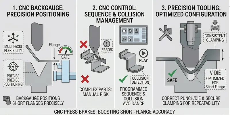
When manufacturing parts with short flanges, the machine’s positioning capability and tooling configuration become particularly important. A CNC press brake cannot eliminate the geometric limitations of an undersized flange — but an appropriately configured machine helps operators control positioning, bending sequences, and repeatability.
CNC backgauge systems. The backgauge determines workpiece positioning before each bend. For parts with narrow or asymmetrical flanges, additional positioning axes provide greater flexibility; CAMT’s 2-, 4- and 6-axis configurations support independent lateral and vertical positioning for more complex workpiece geometries.
CNC control and bending sequence management. A suitable CNC control system helps operators program multiple bending operations and manage positioning parameters. For complex components, offline programming and collision detection identify potential interference before the production run — particularly useful when a part combines short flanges, multiple bends, or narrow return sections.
Precision tooling and clamping systems. Even a high-accuracy press brake cannot compensate for unsuitable tooling. Correct punch-and-die selection, secure clamping, and consistent tool positioning are essential for repeatable results; the background on tooling types and standards in our press brake tooling guide explains what the machine is working with. CAMT provides tooling configurations and clamping solutions matched to the workpiece geometry, required bending force, and production conditions.
Technical support and process optimization. When a flange is close to the tooling limit, a technical evaluation can determine whether a different V-die, custom tooling, or machine configuration is required. CAMT provides technical support covering machine applications, troubleshooting, and operational guidance — for assistance with a specific bending application, visit CAMT Technical Support.
8. Common Mistakes When Calculating Minimum Flange Length
Even experienced operators encounter problems when minimum flange guidelines are applied without the complete bending setup in view. The table below combines the most frequent calculation errors with the failure symptoms they produce at the brake:
| Mistake or symptom | Why it causes problems | Recommended approach |
|---|---|---|
| Using material thickness as the only calculation factor | Ignores the actual V-die opening, which governs the check | Calculate from the selected die opening |
| Treating 0.7V as a guaranteed limit | Actual shoulder geometry may require more support | Check the manufacturer's tooling chart |
| Selecting the narrowest available die | Raises tonnage, shrinks the inside radius, risks the 5t floor | Verify machine and tooling capacity together |
| Applying the 90° estimate to acute bends | Deeper punch travel demands a longer flange | Re-screen with the angle-adjusted multiplier |
| Edge dips into the V at the start of the stroke | Flange shorter than half the opening — no support past center | Measure the flange against 0.7 × the installed die; re-gauge or change the die |
| Angle drifts from part to part on an identical setup | Edge riding at the shoulder brink; the support-loss point moves with placement | Add margin or drop to a narrower die — a marginal flange is not fixed by program tweaks |
| Confusing inside and outside flange dimensions | Produces incorrect comparisons against the chart | Follow one consistent dimension convention |
| Ignoring backgauge positioning | The part cannot be located consistently | Check gauge finger contact and clearance |
| Skipping trial bending | Theory does not reflect production conditions | Validate with actual material and tooling |
The thread running through all of them is the same: the minimum flange length is a property of the tooling setup, not of the sheet. The selected V-die, bend angle, and tooling design all influence the result.
9. Frequently Asked Questions About Minimum Flange Length
What is the minimum flange length for a press brake?
For conventional 90-degree air bending, a common preliminary estimate is approximately 0.7 times the V-die opening, with 0.77 × V as a more conservative guideline. The actual minimum depends on tooling geometry, material properties, and the bending process.
How do you calculate minimum flange length from material thickness?
First estimate the V-die opening using a material-specific guideline — mild steel commonly starts from approximately eight times thickness. Then apply the flange factor: 0.77 × 8t gives a derived planning estimate of about 6.16t. Remember that this stacks two assumptions and is not a universal thickness-based requirement.
Can a press brake bend a flange shorter than the recommended minimum?
Sometimes, with careful evaluation. A narrower V-die or specialized tooling may allow shorter flanges, but the reduced opening increases bending force and affects the inside radius — and below roughly five times the material thickness, accuracy and safety degrade. Always verify tooling capacity, material behavior, and machine compatibility before production.
Does a thicker sheet always require a longer flange?
Not necessarily. A thicker sheet often leads to a wider V-die, which increases the estimated minimum — but the relationship runs through the selected opening and the material-specific bending requirements, not through thickness alone.
Does the minimum flange length change with bend angle?
Yes. The 0.7V and 0.77V guidelines apply to standard 90-degree air bending. For a 30-degree die the multiplier is about 1.5 times greater, and acute dies generally require 110 percent of the opening or more. Bottoming, coining, and special forming operations follow their own tooling data.
Is minimum flange length the same as minimum bend length?
No. Minimum flange length is the shortest flange dimension that can be formed with a particular tooling setup; minimum bend length generally refers to the minimum length of the bend line or workpiece width along the tooling. They are different constraints and should not be confused during part design.
10. Conclusion: Calculate First, Verify the Tooling, Then Bend
Minimum flange length is a core consideration in sheet metal design and press brake tooling selection. The 0.7V and 0.77V formulas provide convenient preliminary estimates, and the bend angle adjusts them — but successful production requires more than arithmetic. Evaluate the actual V-die opening, punch and die geometry, backgauge positioning, and machine capacity before approving a short-flange component, and leave margin between the calculated minimum and the production flange.
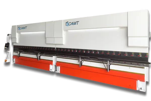
If your production involves narrow flanges, complex profiles, or frequent tooling changes, the right press brake configuration makes a significant difference in setup efficiency and bending consistency. CAMT provides CNC press brakes, customized tooling, backgauge configurations, and technical support for sheet metal manufacturers. If you are evaluating equipment or tooling for short-flange applications, contact CAMT with your material specifications, component drawings, and production requirements for a suitable technical solution.