A press brake can form a sheet metal part to the programmed angle under load, yet the angle may open by several degrees once the punch retracts. This phenomenon, known as springback in sheet metal bending, is a common cause of dimensional errors, inconsistent batches, repeated setup adjustments, and rejected parts. It becomes particularly challenging when bending stainless steel, high-strength steel, aluminum alloys, or parts with large bend-radius-to-thickness ratios.
The solution is not simply to increase bending force. Manufacturers need to understand how material properties, bend geometry, tooling, and machine control influence elastic recovery. By combining springback estimation, controlled overbending, accurate angle measurement, and suitable press brake configurations, fabricators can achieve more predictable bending results and reduce production rework.

What Springback Is and Where It Comes From
Bending stretches the outer surface of the sheet and compresses the inner surface. The outer fibers, under tension, carry more stress than the compressed inner fibers, and when the forming load is removed the elastic portion of both recovers. The tension side wins, so the part unwinds: the angle opens and the bend relaxes toward flat. As one press brake reference puts it, springback is caused by the difference between the tensile forces on the outside of the bend and the compressive forces on the inside, in this explanation of large-radius bending behavior.
Two details matter for daily work.
- The radius opens as the angle opens. The two relax together: the inside radius grows while the included angle widens. A part programmed with a 3 mm inside radius on the machine may measure slightly larger once released.
- The springback happens at unload. An angle checked while the sheet is still under load is not the angle you will ship. Measure with the ram retracted and the part off the die.
What Makes Springback Worse
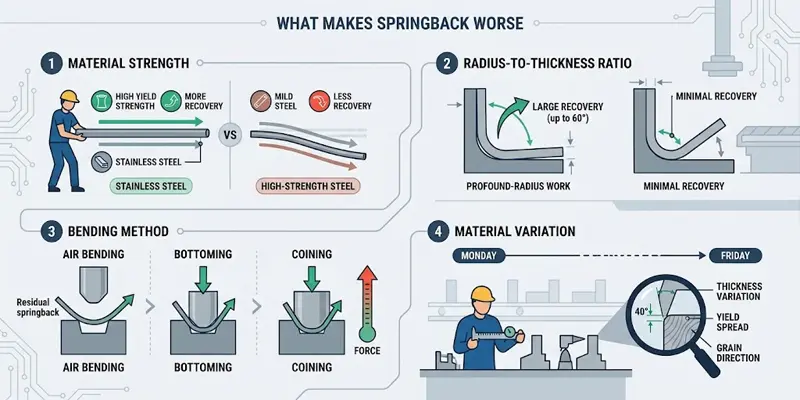
Four factors drive the amount of recovery, and each one points at a different lever.
Material strength. Higher yield strength means a larger elastic share of the deformation, so more of it recovers. Stainless steel springs back more than mild steel, high-strength steel more than stainless, and within aluminum, heat-treated tempers such as 6061-T6 fight harder than soft 5052-O. A steelmaker’s bending reference puts the ranking plainly: springback increases with the yield point, with strain hardening and with die width, and the yield point has the greatest influence of the three, as SSAB describes in its press bending guide. Work-hardening during bending adds to this: a bend made and then re-bent to correct it behaves differently from a single hit.
Radius-to-thickness ratio. This is the factor operators underestimate most. A tight bend with an inside radius close to one material thickness recovers only a few degrees. As the radius grows relative to thickness, the elastic share grows with it. In profound-radius work — an inside radius beyond eight times the thickness — springback can reach 60 degrees in newer high-strength steels, according to the same bending reference. A “90° bend” in that territory is really a multi-stage forming problem, not a depth setting.
Bending method. Air bending concentrates plastic deformation in a narrow zone and leaves the most elastic recovery. Bottoming presses the sheet into the die walls and reduces it. Coining, which cold-forges the bend zone, nearly eliminates it. The trade-off is force: both processes demand substantially more than air bending, the exact amount depending on material, tooling and how the operation is defined, and the machine, toolholders and die must be rated for it.
Material variation. Thickness tolerance, yield spread within a grade, grain direction and the heat-affected edge from laser cutting all shift the recovery. This is why the same program can measure differently on Monday’s sheet than on Friday’s, even when nothing on the machine changed.
Is It Really Springback? Read the Error Pattern First
Before calculating anything, confirm that springback is what you are fighting. In uniform material with uniform tooling and machine condition, springback tends to show up as a consistent offset: the same extra degrees on every part, repeated along the bend line. But that pattern is a tendency, not a law. Sheet thickness varies within a panel, yield strength varies within a coil, rolling direction changes the recovery across the bend line, and uneven loading can leave the ends and the middle recovering differently. Uneven springback is possible, and an angle that varies along the length is not automatic proof that springback is innocent.
The table below separates the common angle and dimension problems by their typical behavior:
| Problem | Typical characteristic | Main cause |
|---|---|---|
| Springback | Bend angle opens after unloading | Elastic recovery |
| Angular variation along the length | Center and ends show different angles | Beam deflection or crowning |
| Uneven left-right angles | Different angles at both ends | Ram synchronization or tooling alignment |
| Batch-to-batch angle changes | Same program produces different results | Material property variation |
| Flange dimension errors | Incorrect flange length despite acceptable angle | Bend geometry or flat-pattern calculation |
Two lookalikes deserve special care. When the middle of the part is open while the ends are correct, the cause is frame and ram deflection, not material memory — see our guide to why the bend angle changes along the part. And when the offset appears only after a tool change or on one station of the backgauge, the tool height, seating or program data is the suspect, not the material.
The habit that prevents misdiagnosis: measure five points along the bend on three consecutive parts before touching a setting. The pattern of the error, not its size, names the cause. If you are unsure which defect you are chasing, the press brake troubleshooting guide walks through all of them in diagnostic order.
Typical Springback Numbers, and Their Conditions
Rules of thumb are only useful when you know the conditions they assume. The table below is anchored to one widely cited set of shop values for air bending, published in a deep-box forming guide.
| Material | Typical springback (air bend) | Assumed conditions |
|---|---|---|
| Cold-rolled mild steel, light gauges | 0.5° – 1° | Inside radius ≈ 1 × thickness |
| Aluminum | 1.5° – 2° | Inside radius ≈ 1 × thickness; alloy and temper vary widely |
| 304 stainless | 2° – 2.5° | Inside radius ≈ 1 × thickness; annealed sheet |
Three cautions apply before you copy any of these into a program.
- The 1-to-1 ratio is doing the work. At a 2-to-1 or 3-to-1 radius-to-thickness ratio, the same grades recover noticeably more than the table shows. At profound radii, the table concept stops working entirely.
- Alloy and temper move aluminum across a wide band. Soft 5052-O behaves closer to mild steel; 6061-T6 lands well above the table value and varies batch to batch.
- A different mill can shift the number. Tensile strength varies within a grade’s specification. The same 304 from a different source can recover a different amount, which is why per-batch verification exists.
Estimating Springback: The Empirical Formula and the Gardiner Model
Two estimation tools exist, and they do different jobs. The first gives a quick number for the job at hand; the second explains where the number comes from and why it moves. Neither replaces a test bend.
A first-pass empirical estimate
One published shop method treats springback as a function of the punch radius and thickness. For 60,000-psi cold-rolled steel — its explicit baseline — the estimate is the punch radius divided by the material thickness times 0.9, divided by two; for other materials, multiply the result by a material factor equal to the tensile strength divided by 60,000 psi, as set out in this bending calculation guide.
Worked example, mild steel:
- Punch radius 3 mm, sheet 3 mm thick (a 1-to-1 ratio), tensile strength near the 60,000-psi baseline.
- Estimate: 3 ÷ (3 × 0.9) ÷ 2 ≈ 0.56°.
- That lands inside the 0.5° to 1° band in the table above, which is what the formula is calibrated for.
Treat this as what it is: an empirical rule calibrated on one baseline material, useful for sizing the first correction and for spotting when a drawing’s radius request will push springback far outside normal range. It is not a material model, and it should not be expected to transfer cleanly to other grades.
The Gardiner model: where the physics lives

The classical analytical treatment comes from Gardiner, who modeled a sheet under pure bending as an ideal elastic-perfectly-plastic material. In the common formulation, with x = (Y × Ri) ÷ (E × t), where Y is the yield strength, E the elastic modulus, Ri the inside radius before unloading and t the thickness, the ratio of loaded to unloaded radius follows Ri/Rf = 4x³ − 3x + 1. A study in the International Journal of Mechanical Sciences, which re-derives and extends Gardiner’s solution, states the same relationship in the form ρb/ρa = 1 − 3(σs·ρb/(E·t)) + 4(σs·ρb/(E·t))³ and draws out the practical reading: springback increases with the radius-to-thickness ratio and the yield stress, and decreases with the elastic modulus.
The model explains the behavior we see at the brake. Aluminum’s low modulus makes it springy relative to its strength; a generous radius on high-strength steel multiplies recovery; thicker sheet at the same ratio dilutes the elastic share. What the model does not do is hand you a production setting. It assumes ideal elastic-perfectly-plastic behavior and pure bending — no work hardening, no friction, no tooling contact effects beyond the idealized geometry. Real materials strain-harden, and real bending deforms with a deformation history the simple model ignores. The same journal study proposes an improved prediction formula that adds a hardening component and shows better agreement with experimental data than Gardiner’s original solution, which is a fair warning about how much the simplified form can miss.
For the full mechanics of bending and springback, ASM Handbook Volume 14B (Metalworking: Sheet Forming) carries dedicated chapters on bending of sheet metal and on springback, available from ASM International. The practical conclusion for the shop floor stands regardless of the model’s sophistication: every published springback number, whether from a rule of thumb, a formula or an analytical model, is a starting guess for the first test piece, not a setting to trust in production.
The radius you program also depends on the die. In air bending, the inside radius is set by the V-die opening at roughly 0.16 to 0.17 times the opening, for standard sheet work — so a shop that needs a specific radius-to-thickness ratio often reaches it by choosing the die opening first, using the common 6-to-8-times-thickness range and adjusting for the material and the target radius.
What Springback Does to the Final Part
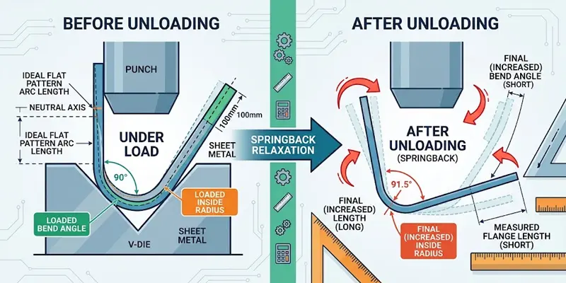
Springback changes two things at once: the final bend angle and the final inside radius. Because those two moves are linked through the geometry of the bend, their combined effect on part dimensions is subtler than either change alone.
In an idealized pure bend, the arc length of the neutral layer — the sheet’s unchanging reference through the bend — stays essentially constant as the part relaxes: the inside radius grows while the included angle widens, and the two changes offset each other along the arc. Real bends are not that clean. Contact with the punch and die, friction and local deformation mean the unloaded geometry can differ from the loaded geometry in ways the simple picture does not capture, and on a multi-bend part those differences show up where the dimensions are checked: flange lengths.
The practical consequences:
- Flange dimensions are computed from the final geometry, not the loaded geometry. If the flat pattern was built on the radius and angle the tool produced under load, and the part relaxed beyond that assumption, the flanges nearest the affected bends can come out measurably long or short even when every individual angle passes inspection.
- Verify both angles and flange dimensions on the first article. A coupon tells you the angle correction; a first article tells you whether the flat pattern assumptions survived unloading.
- Trust validated geometry. When a part runs close to tolerance, feed the measured final angle and radius back into the flat-pattern calculation rather than the nominal tool geometry.
The full flat-blank mathematics behind this — bend allowance, bend deduction and the K-factor — is its own subject and is covered in our bending guide. For springback control, the working rule is simpler: if lengths drift by a consistent amount while angles hold, compare the geometry the program assumes against the geometry the part actually keeps after unloading.
The Test Bend Decides

Because published numbers disagree, the coupon is the arbiter. The workflow costs one or two pieces of scrap from the current batch.
- Cut the coupon from the same sheet or coil the production parts will come from. Scrap from a previous order proves nothing.
- Form at the estimated setting — the included angle tighter than target by the estimated springback, from the formula or table above.
- Release, then measure. Ram retracted, part off the die, one angle convention, recorded to a tenth of a degree. A digital angle gauge or protractor does this job on the bench; in-process angle measurement systems do it at the machine, which is what closed-loop correction builds on.
- Adjust the forming angle once by the difference between measured and target angle, and re-bend a fresh coupon if the correction is large. Depth per degree changes with the V opening, so carry the correction per job, not per machine.
- Record the verified correction in the job’s setup data — against material grade, thickness, V opening, supplier and target angle — so the next run of the same part starts from the measured value instead of the published guess. Over a year this becomes the most valuable springback table in the shop, because it is your material, your tooling, your machine.
For one-off work where a coupon is not practical, expect the first part to be the coupon, and choose the process accordingly — which is exactly what closed-loop angle correction was invented to avoid.
Four Ways to Compensate
Overbending in air bend
The default method. Form the part to an included angle tighter than the drawing calls for, so it relaxes onto the target angle as it springs back. It costs nothing in tooling and works with one die across many angles, which is why air bending dominates modern shops. The cost is process discipline: every new grade, thickness or batch needs its correction re-verified, because the overbend that fixes mild steel will over-close stainless.
Bottoming and coining
Pressing the sheet fully into the die — bottoming — enlarges the plastic zone and cuts springback sharply; the angle follows the tool far more closely than in air bending, though material variation and die fit still leave some recovery. Coining goes further and reshapes the bend zone under local pressure, reducing recovery to near zero. Both demand dedicated per-angle tooling and substantially more force than air bending — the exact multiple depends on the material, the tooling and how the operation is defined, so the force must be calculated for the actual job and checked against the machine rating, the die load limits and the toolholder capacity. They buy repeatability at the price of flexibility, which is why they suit fixed-angle, high-volume parts rather than mixed work.
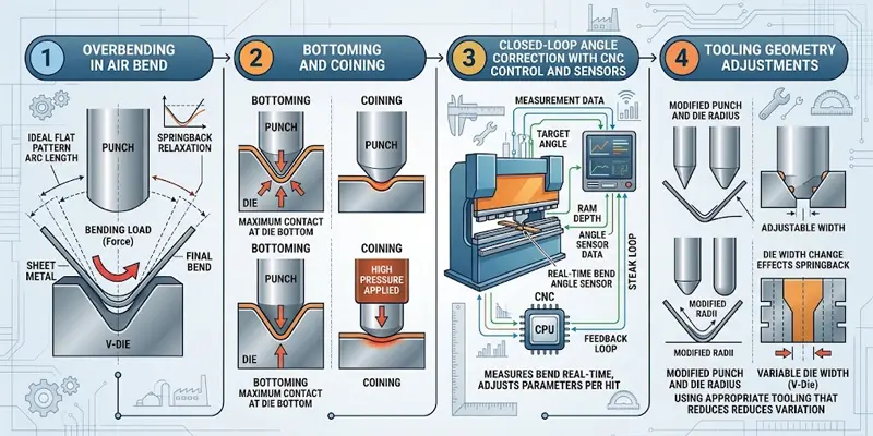
Closed-loop angle correction
The compensation that does not depend on anybody’s table. An angle measurement system monitors the actual bend angle during forming. Depending on the system configuration, the CNC control uses the measured angle and its compensation model to adjust ram penetration, accounting for the springback expected after unloading. This absorbs batch-to-batch variation, a different mill’s sheet, even a worn tool edge, without relying entirely on manual correction. This is the configuration we build around on our CNC press brake control systems, available on machines such as the Genius 4-to-6-axis CNC press brake, and it is the practical answer for shops running stainless, high-strength material or mixed batches where a verified table from Monday cannot be trusted on Tuesday.
Tooling geometry
Less visible but real: acute punches, relieved dies and compensated die angles push material around the punch in ways that pre-load the springback. They matter most in large-radius and high-strength work, where a standard 90° V die has no answer for a 30° recovery.
| Method | Repeatability | Tooling cost | Force demand | Best fit |
|---|---|---|---|---|
| Overbending (air bend) | Good, if verified per batch | None beyond standard V tooling | Lowest | Mixed angles, general work |
| Bottoming | Very good for one angle | Dedicated die per angle | Substantially higher — calculate per job | Fixed-angle production parts |
| Coining | Near total | Dedicated, hardened tooling | Highest — calculate per job | Tightest tolerances, thinning acceptable |
| Closed-loop angle correction | Very good across batches | Angle measurement hardware | Same as air bend | Stainless, HSS, mixed batches |
Choosing a Method for the Job
Map the part’s requirement to the lever:
| Your situation | Reach for |
|---|---|
| Mild steel, ±1° acceptable, mixed angles | Air bending with a table-informed overbend, verified on the first piece |
| Stainless or high-strength parts, repeat orders | Closed-loop angle correction, or bottoming if angles are few |
| Angle tolerance below ±0.5° | Bottoming or coining, with the force calculated for that method |
| Inside radius beyond 8 × thickness | Treat as a forming problem: compensated tooling, staged bending, simulation |
| New supplier or new batch of a familiar grade | Re-run the coupon regardless of method |
One boundary deserves emphasis: compensation never changes the force requirement. If the drawing pushes a bend toward bottoming territory, calculate the tonnage for that method, not for air bending, and check it against the machine rating and the die load limits before the first stroke.
A Real Job, From Estimate to Shipment
Watch the pieces fit together on a typical job: a bracket in 2 mm 304 stainless, target angle 90° included, inside radius specified at 2 mm — a 1-to-1 ratio. For this example, assume the drawing allows ±0.5° on the angle. That tolerance is a case assumption, not an industry standard; acceptance always comes from the drawing and the customer.
Setup. The table gives 2° to 2.5° of expected springback for this grade and geometry. The V-die selection follows from the radius: air bending puts the inside radius at roughly 0.16 to 0.17 of the V opening, so a 12 mm V lands near the 2 mm target. The program starts with a forming angle of 87.5° — about 2.5° tighter than the required 90° included angle, taking the top of the table’s estimate so the first attempt errs on the closed side.
First coupon. The coupon, cut from the production sheet, releases at 90.2° — 0.2° open of target, which lands inside the assumed ±0.5° band and would ship. For margin, the forming angle is tightened by the measured difference to 87.3°, and the second coupon releases at 90.0°. Measurement is by digital angle gauge on the bench, with the correction recorded in the job’s setup data against grade, thickness, V opening and supplier, so the next run recalls the verified value instead of the published estimate.
Mid-run surprise. Two hundred parts in, a new pallet of the same grade arrives from a different mill. Parts start releasing at 90.6° — the new batch carries a slightly higher yield strength, pushing the released angle outside the assumed band. On a manually corrected setup this is the moment an operator catches it at inspection, hopefully before scrap accumulates. With in-process angle measurement closed back to the control, the system sees the drift and re-corrects the ram position without stopping the run.
The lesson in the numbers. Notice what the shop never did: it never trusted the table beyond the first guess, and it never guessed the direction — the forming angle is always tighter than target, and the released angle opens back toward it. The table aimed the first coupon; the coupon set the real correction; the measurement system absorbed the batch change. Every published springback figure served as a hypothesis, and measurement promoted or retired it. That discipline — estimate, verify, close the loop — is the whole method, and it scales from a single bracket to a production run of enclosures.
Frequently Asked Questions
How many degrees should I overbend for a 90° bend in mild steel?
Whatever the coupon says. Typical air-bent mild steel at a 1-to-1 radius-to-thickness ratio recovers 0.5° to 1°, so that is a sane first guess, and it grows with the radius. Form the first piece to an included angle tighter than 90° by the estimated amount, measure after release, and correct once. The reliable number is always the measured one from the current batch, because tensile strength varies within every grade’s specification.
Why does stainless steel spring back more than mild steel?
Its yield and tensile strength are higher, so a larger share of the bend is elastic. Type 304 also work-hardens as it forms, adding recovery on top. Expect roughly double the mild-steel figure at the same geometry, and more again if the radius is larger relative to thickness.
Does thicker material spring back more?
In an idealized bending model, springback is governed mainly by the ratio between bend radius and material thickness, so two bends with the same radius-to-thickness ratio and comparable material properties show similar theoretical recovery, whether the sheet is 2 mm or 10 mm. Actual press brake work adds thickness-dependent factors the ratio does not capture: stress distribution through the thickness, tooling scale and contact conditions, machine deflection under higher loads, and the strength and hardening behavior of the grade itself. In production, thickness alone does not determine springback — and thick plate is usually bent at generous radii anyway, which is what pushes its recovery up.
Can bottoming eliminate springback completely?
It reduces it sharply, because the sheet conforms to the die walls and the plastic zone grows, but material variation and die fit usually leave a small recovery. Coining comes closer to eliminating it by cold-forging the bend zone. Both need substantially more force than air bending — calculated for the actual job — plus per-angle tooling, and a machine and die set rated for the load.
Do CNC press brakes compensate for springback automatically?
Partly, and it depends on the control. Many advanced CNC press brake controls support programmable springback compensation based on material and tooling data when they calculate the punch depth. Automatic closed-loop correction goes further: it requires compatible angle measurement hardware and control functionality, with the system monitoring the formed angle and the control adjusting ram penetration against its compensation model. That is the configuration we recommend for stainless and high-strength work, described in the closed-loop section above.
Is springback the same on every press brake?
The material’s recovery is the same everywhere; what differs between machines is how well the depth is held and how the correction is applied. Ram positioning accuracy and the control’s correction model decide how close the first part lands, and an angle measurement loop decides whether the second part needs an operator or not.