When a press brake produces flanges that are consistently too long, too short, or different from one part to the next, adjusting the backgauge position seems like the obvious fix. It often is not. A press brake bend dimension error on flanges comes from two families of causes: the backgauge — where the sheet actually sat relative to where the control believed it sat — and the material — what the sheet actually was, and what the bending data assumed about it, before the ram came down. Shops that separate the two families fix flange problems in minutes. Shops that don’t spend the afternoon stacking offsets that never hold.
At a glance
- Every flange consistently too long or too short, on every part: a reference, program data, blank size, or bend deduction problem. Measure the blank before touching the gauge.
- The dimension creeps in one direction as the run progresses: mechanical drift in the backgauge, not a setup issue.
- Left and right flanges disagree, or the flange tapers along the bend: finger alignment, seating, or blank squareness.
- Dimensions scatter randomly part to part: material edges and seating inconsistency.
- The error arrived with a new material lot: thickness and strength tolerances changed what the bend consumes.
- First bend accurate, later bends drift: datum selection or accumulated multi-bend error.
- The error started right after a tooling change: the die width changed the inside radius, and the flat-pattern math no longer matches the tooling.

Where the Flange Dimension Actually Comes From
A flange dimension is the end of a chain, not a single setting. The chain runs: the programmed flange size, converted through the bend deduction into a flat-blank dimension; the blank as actually cut; the position of the gauge fingers; the sheet seated against those fingers; the bend itself; and finally the measurement. The flange comes out right only when every link agrees with every other link.
The flat-pattern link is worth spelling out, because it is the one most often skipped during troubleshooting. On the drawing and the flat blank, the outside mold line location corresponds to the flange’s outside dimension, and the inside mold line sits one bend deduction below it; subtracting each bend deduction from the stack of outside dimensions gives the flat-blank size (The Fabricator).

That chain breaks in three distinct ways, and a 30 mm flange shows the difference:
- A positioning error sets the bend line in the wrong place: the gauge holds the sheet 1 mm off the programmed reference, so every bend lands systematically displaced. One caution — a 1 mm gauge displacement should not automatically be read as a 1 mm error in every finished dimension, because the relationship between gauge movement and finished size depends on the part geometry and the measurement reference.
- A material variation leaves the gauge exactly where it should be, but a different thickness or bending response changes the formed geometry.
- A calculation error positions and bends the sheet accurately, but the programmed bend deduction does not match the actual material and tooling.
The distinction matters because the corrections differ: a positioning error changes where the bend occurs, while material and calculation errors change the relationship between the flat blank and the finished part. Read the error signature first and the list of suspects drops from a dozen to two or three.
Read the Error Signature Before Touching Anything
Resist the urge to re-home the gauge or edit the program on the first bad part. Every flange error leaves a signature: how big it is, whether it repeats, where it sits on the part, and when it started.
| What you observe | Most likely family | The test that separates it |
|---|---|---|
| Same offset on every part, identical at both ends of the bend | Backgauge reference, program data, blank size, or bend deduction | Compare displayed X with the physical finger position; measure the blank |
| Dimension drifts in one direction through the run, or scatter grows worse | Backgauge mechanics: backlash, debris, wear | Run gauging cycles without bending and record where the finger actually lands |
| Left and right flanges disagree, or the part tapers along the bend | Finger alignment, seating, or blank edge condition | Seat the sheet against one finger at a time; check blank diagonals and edges |
| Dimensions scatter randomly part to part | Material edges and seating inconsistency | Micrometer the batch; inspect burrs, scale and cut edges |
| The error moved in with a new material lot | Material tolerance zone | Compare measured thickness and a test bend against the previous lot |
| First bend accurate, later bends drift | Datum selection, accumulated multi-bend error, or repositioning | Review the bend sequence and how each bend references the last |
| The error appeared immediately after a tooling change | Program and tool data | Recalculate the bend deduction for the new die width |
Two of these rows deserve a warning. A constant offset that repeats perfectly is deterministic, which means it will also reproduce perfectly after you “fix” the wrong thing. And random scatter is the signature where chasing the backgauge rarely pays, because a positioning system that repeats to its specification cannot produce randomness on its own.
Backgauge Cause 1: The Reference You Think You Have
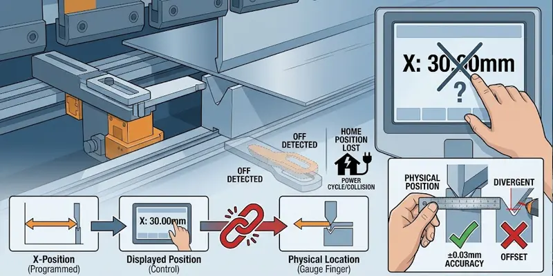
Three values must agree for a flange to come out on size: the X position the program calls for, the position the control displays, and the physical location of the finger face relative to the die. A flange error that is identical on every part usually means two of these three have quietly diverged.
The usual suspects are an offset left over from the previous job, a program reused after the material thickness, tooling, bend angle or sequence changed, a finger bumped during loading or die changes, or a home position lost after a power cycle or a collision. The control reports where it believes the axis is; it cannot detect that a finger was knocked or that an offset was never cleared.
One trap in this family catches even experienced setters: the backgauge position is not the same number as the finished flange dimension on the drawing. The control computes the X value from the bend geometry and the dimensioning method, so typing a 30 mm drawing dimension in as a 30 mm gauge position can be wrong before the machine moves. Verify what the program’s gauge value represents before assuming the program itself is at fault.
The separating test is direct. With the machine in a safe state, compare the displayed X value against the physical finger position, measured the way your control defines its reference. On a healthy system the two agree within the manufacturer’s specification — CAMT backgauge systems, for example, are built to hold ±0.03 mm positioning accuracy across their 2-axis to 6-axis configurations (see the backgauge system selection page for what each axis contributes). If the displayed value and the physical position disagree, you have found your constant offset, and no amount of program editing will make it go away.
Backgauge Cause 2: Drift That Grows Through the Run
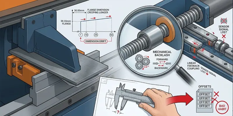
The second backgauge signature is the opposite of a constant offset: the dimension changes over time. Flanges creeping longer or shorter as the batch progresses, or a first article that drifts out of tolerance by part fifty, point at the gauge’s mechanical chain rather than its reference.
The inspection list is short and physical: ball screws and drives, linear guides and bearings, couplings, encoder feedback, and the finger mounting assemblies. Backlash has a recognizable signature — the axis arrives at slightly different physical positions depending on whether it approached the coordinate moving forward or backward, which matters most in production that steps repeatedly between different flange dimensions.
Confirm it without bending a single part: command a series of gauging cycles to the same position, approach it from both directions, and record where the finger actually settles each time. If the positions wander, the gauge needs mechanical attention before the next production run. This is also the moment to resist the most common bad habit in flange troubleshooting — stacking ever-larger offsets onto a drifting axis. An offset corrects one program for one afternoon; mechanical play comes back tomorrow, in every program.
Backgauge Cause 3: The Sheet Never Sat Where You Think
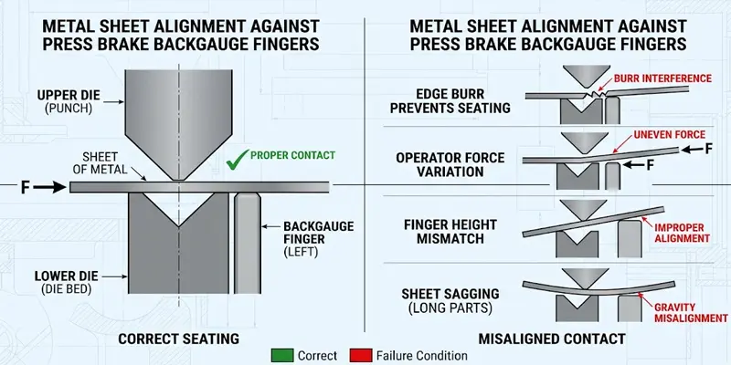
A gauge finger can be exactly where the control says it is and the flange can still come out wrong, because the flange is set by where the sheet edge sat, not where the finger sat. Anything that comes between the two belongs to this group.
- Burrs, scale or dross on the blank edge. A cut edge with a heavy burr lets the sheet bridge on the burr tips instead of seating flat against the finger face, moving the effective gauge line by the burr height.
- Operator seating force. Too light a push leaves a gap; too hard a push on thin, smooth sheet can bowl the blank or slide it under the finger. Different operators, different flanges, same program.
- Finger height. If the finger top face is not matched to the sheet and die combination, the sheet can climb the finger during the stroke instead of staying registered against it.
- Finger alignment and beam parallelism. If one finger sits farther forward than the other, or the gauge beam is not parallel to the machine reference, a long blank contacts the fingers unevenly — which is exactly where the left-versus-right flange signature comes from.
- Long or flexible blanks. A wide sheet that sags, rocks or carries residual stress from cutting cannot seat the same way twice.
The left-right disagreement deserves its own test: seat the sheet against the left finger only, then the right finger only, then both, and bend a test piece each way. If the flange changes with the seating method, the cause is contact and seating, not the gauge’s position. On large blanks this is the failure mode that powered sheet support exists to remove — the sheet is held against the gauging surface through the stroke instead of being managed by hand.
Material Cause 1: The Blank Was Never the Size You Programmed
Before blaming any machine component, measure the blank. This is the cheapest check in flange troubleshooting and the most frequently skipped, because a cutting error and a gauging error look identical in the finished part.
Three blank-side failures produce flange errors that mimic backgauge faults perfectly:
- Cutting tolerance. The laser, plasma or shear that produced the blank has its own accuracy budget. A blank cut a few tenths of a millimeter oversize produces flanges a few tenths long, identically on every part, with a perfect backgauge.
- Flatness, camber and residual stress. A blank that is warped, twisted or unevenly stressed cannot sit consistently against the fingers, and it can distort further as cutting heat and bending loads release what is locked inside it. Lay a suspect blank on a flat surface and check for bow and twist before bending it; if the material is distorted before it reaches the press brake, no gauge adjustment will remove the cause.
- Wrong edge, wrong flange. On parts gauged from a cut edge with heavy dross, the effective dimension changes with the edge condition — and the edge condition changes along the cut.
The blank-first habit is simple: for any recurring flange complaint, check the blank dimension that sets the flange, at the edge that gauges against the finger, before anything else on the machine is touched. If the blank is wrong, the press brake was never the problem.
Material Cause 2: Tolerances That Move the Finished Dimension

Material that meets specification can still move a flange dimension, because “to specification” is a tolerance zone, not a single value. A drawing may call 2.0 mm steel, but the actual sheets vary within the mill’s allowable range — measure several points on several sheets, not one reading on one sheet. Yield and tensile strength vary more than most shops assume, and ASTM standards set those allowable variations, not the tolerance block on the print (The Fabricator).
Here is the mechanism, because it explains why the error shows up in a dimension rather than only in an angle. The flat blank was developed with a bend deduction calculated for nominal thickness and strength. When the actual sheet is thicker, stronger, or rolled anisotropically, the bend consumes a slightly different amount of material than the deduction predicted, so the finished flange measures off the print even though the gauge placed the blank edge exactly where the program asked. The same article notes that grain direction changes bending results and requires different bend deductions — so a new batch nested differently can shift flange dimensions on a machine that has not been touched.
Treat thickness as a controlled process input for tight-tolerance work: record the measured value, not the certificate nominal, and keep blank orientation consistent between runs so grain direction does not become an uncontrolled variable. The signature gives the cause away: the error arrived with a new coil or lot and disappears when the old material returns.
Bend Data and Measurement References: The Errors Hiding in the Numbers
Not every wrong flange comes from mechanics or metal. Sometimes the machine positions and bends the sheet exactly as programmed, and the programmed numbers were wrong for the job.
The tool-data chain is the most common version. As Cincinnati Incorporated’s bending product manager puts it, the die opening determines the inside bend radius, the radius determines the blank size, and “when you use the wrong V die width or angle, you throw off your flange dimensions” (The Fabricator). A job set up for one die and run on another forms a different inside radius; the bend deduction baked into the flat pattern no longer matches; every flange comes out off, consistently, on a perfectly healthy gauge. The tell is timing: the error started the day the tooling changed.
Behind that chain sit two numbers worth understanding. The bend allowance is the length of material along the neutral axis through the curved bend region — in plain terms, BA = π/180 × bend angle × (inside radius + K-factor × thickness). The bend deduction is what you subtract from the sum of outside flange dimensions to get the flat blank, built from the outside setbacks and the bend allowance. Both depend on the material, thickness, bend angle, radius and forming method; when the values in the program do not match the conditions in the machine, flange dimensions go wrong even with repeatable gauging. (A full treatment of K-factor and flat-pattern development is a topic of its own; for troubleshooting, the practical rule is to validate the stored deduction with a measured test bend rather than trusting theory.)
One more numbers problem is invisible until someone measures it: the drawing reference. A flange dimension may be drawn to the inside surface, the outside surface, the tangent point of the bend, or the theoretical intersection of the extended surfaces — and these are not interchangeable. A part can look like it has a wrong flange when measured outside while the drawing specifies an inside dimension. Before changing any machine setting, confirm the inspection method measures the same reference the drawing dimensions.
A Controlled Way to Attribute the Error
When the signature alone does not settle it, isolate one variable at a time:
- Confirm the drawing and the measurement method. Dimensions, tolerances, bend angles, radius, material, and which surface the dimension references.
- Measure the blank that sets the flange, at the edge that gauges against the finger.
- Compare displayed and physical gauge position, and run the repeatability test above.
- Micrometer the batch at several points on several sheets, and inspect edges for burrs and dross.
- Bend controlled test pieces — identical blanks, same program, tooling, gauge reference, sequence and material orientation. Consistent-but-wrong results point to program data and offsets. Varying results point to material, seating and repeatability.
A worked example shows the sequence in motion. A bracket programs a 25.0 mm flange; every part measures 25.8 mm, identically at both ends, angle on target. The deterministic signature eliminates seating and drift. The blank gauges 25.0 mm to the bend line — cutting is innocent. The control displays X 120.0 mm, but the finger face measures 120.8 mm from the die reference: an offset entered during last week’s die change was never cleared, and every program since has inherited it. Clearing it returns the flange to 25.0 mm. The same five minutes would have found an oversize blank or a stale bend deduction had the signature come out differently — and note what the walkthrough never did: recalibrate on suspicion. Calibration answers a confirmed reference fault, not a hunch; the numbers here are illustrative, and the separating tests are what transfer to your floor.
If the blank measures right, the gauge repeats to specification, the seating is consistent and the program data matches the tooling, the remaining suspects live outside these two families — tooling wear, machine geometry, or an angle error that only looks like a dimension error. Those layers are covered in the full diagnostic framework in Press Brake Troubleshooting: Bending Defects, Causes and Fixes, which sequences every check from cheapest to most expensive.
Keep It Fixed: Process Discipline and When to Change the Configuration
Most recurring flange problems are prevented by a handful of habits:
- Measure the blank on first-article checks for any part with a tight flange tolerance, not just the bent result.
- Record gauge offsets and clear them at job change, so one job’s correction never leaks into the next program.
- Build a material-specific bending database. For each combination, store the material grade, the measured thickness, the punch and V-die specification, the validated inside radius, the verified bend deduction and the approved gauge position. Make programs pull from the library instead of typed-in defaults — the CNC systems CAMT fits, from compact Delem units through 3D graphical controllers with tool, material and product libraries, are built for exactly this (see the CNC control system page to match a controller tier to your job mix).
- Log material lots on tolerance-critical jobs, so a flange shift can be matched against the coil it arrived with.
- Watch the trend, not just the part: a flange creeping a tenth per hundred parts is a maintenance signal — catch it before it is scrap.
- Audit the database after any tooling change, because that is when the deduction silently stops matching the machine.
Sometimes, though, the honest conclusion is that the configuration, not the process, is the limit. The signals: flange accuracy depends on constant manual adjustment; the gauge lacks the axes to handle asymmetrical parts efficiently; repeatability keeps degrading despite proper maintenance; or production steps between flange dimensions all shift long. The goal is not the backgauge with the most axes — a shop running standard panels may be well served by a maintained 2-axis or 4-axis system, while complex enclosures and offset flanges justify independent finger control. Match the configuration to the geometry and the volume, and if the evaluation points to a change, raise the specifics through our contact page with the part drawings and the error measurements.
Sources
- The Fabricator, Press brake bending basics: Going old-school with notch layout
- The Fabricator, Don’t forget the sheet metal tolerances
- The Fabricator, Six steps to create predictable job flow in the press brake department
Frequently Asked Questions
Why are my press brake flange dimensions consistently too long?
The most common causes are an incorrect X-axis position or offset, a bend deduction that does not match the tooling and material, or a blank cut oversize. Check the physical gauge position against the displayed value and measure the blank first, then verify the bend calculation — in that order — before modifying the program.
Can the backgauge be positioned correctly and the flange still come out wrong?
Yes, in two ways. Mechanically, the finger face and the displayed position can disagree after a collision or an uncleared offset — the control reports where it believes the axis is. Physically, the sheet can fail to seat against a correctly positioned finger because of burrs on the blank edge, inconsistent operator seating force, or a long blank rocking during loading. The flange is set by where the sheet edge sat, not where the finger sat.
Can material thickness affect finished flange dimensions?
It can. Actual thickness affects the bend geometry and the amount of material the bend consumes, and the bend deduction used to develop the flat blank assumes a nominal value. When the actual sheet differs from nominal, the finished flange measures off the print even with perfect gauging. The signature is an error that arrived with a new material lot and tracks the batch.
How do I tell a backgauge problem from a material problem quickly?
Read the signature. A constant offset on every part points to reference, program data or blank size — measure the blank first, then compare displayed and physical gauge position. Drift during the run points to gauge mechanics. Random part-to-part scatter points to material edges and seating. An error that moved in with a new coil points to the material tolerance zone.
Does a 4-axis backgauge improve flange dimension accuracy?
It improves positioning flexibility, not accuracy by itself. The Z1 and Z2 axes let the fingers move independently, which helps with different flange heights, asymmetrical parts and complex sequences. It does not correct material variation or an incorrect bend calculation — those errors reproduce just as faithfully on a 6-axis gauge as on a 2-axis one.
Should I add an offset or recalibrate the backgauge?
Decide by what the error is doing. A small constant offset that appears in one program after a setup change is what offsets exist for. A constant offset that appears in every program, or a dimension that drifts, is a reference or mechanical fault, and stacking offsets on top of it hides the cause while it grows. Calibration belongs after the fault is confirmed — a confirmed reference disagreement is exactly what recalibration corrects.