Setting the correct cutting speed is essential for achieving clean edges, consistent dimensions, and high production efficiency with a fiber laser cutting machine. If the speed is too high, the laser may fail to penetrate the material completely, leaving uncut sections and excessive burrs. If it is too low, excessive heat can cause a wider heat-affected zone, rough edges, and unnecessary production time.
This guide explains how to select and adjust fiber laser cutting speed, provides practical reference parameters, and shows how to troubleshoot common cutting defects to achieve a balance between cutting quality and production efficiency.
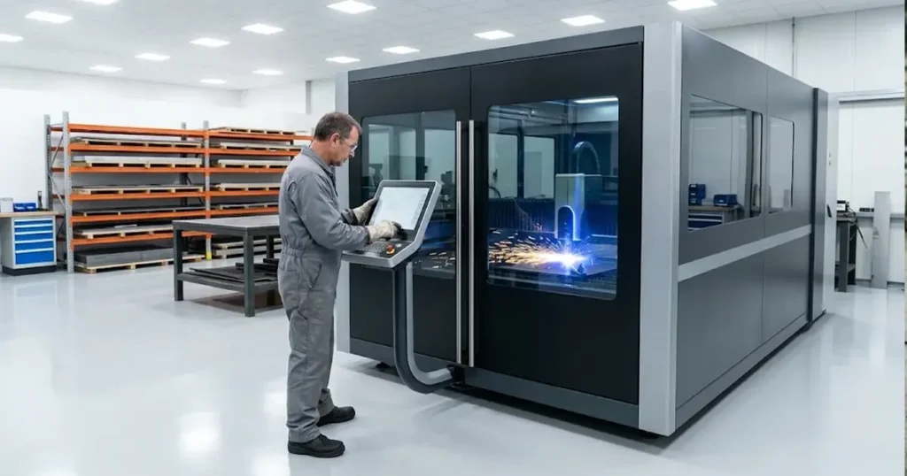
How to use and adjust the fiber laser cutting speed table
| Material | Thickness | Feed, m/min | Gas | Pressure at head, bar | Nozzle, mm | Focus, mm |
|---|---|---|---|---|---|---|
| Stainless 304 | 1 mm | 28–35 | N₂ | 10–12 | 1.2–1.5 | −1 to −2 |
| Stainless 304 | 2 mm | 18–24 | N₂ | 12–14 | 1.5 | −2 to −3 |
| Stainless 304 | 3 mm | 7–10 | N₂ | 14–16 | 1.5–2.0 | −3 to −4 |
| Stainless 304 | 6 mm | 2–2.7 | N₂ | 16–18 | 2.0 | −4 to −5 |
| Stainless 304 | 10 mm | 0.5–0.6 | N₂ | 18–20 | 2.5 | −5 to −6 |
| Aluminium | 1 mm | 25–30 | N₂ | 10–12 | 1.5 | −1 to −2 |
| Aluminium | 3 mm | 7–8 | N₂ | 14–16 | 2.0 | −3 to −4 |
| Aluminium | 6 mm | 1.5–2 | N₂ | 16–18 | 2.5 | −4 to −5 |
Read the row, not the cell. Feed bands come from one 3 kW reference dataset; pressure, nozzle and focus are the ranges comparable 3 kW machines run at to reach them. Lift one cell without the others and you have not copied a setting, you have broken one. Negative focus means below the surface, the convention on most fiber heads — confirm it in your controller first.
Expect to sit outside the band. A 30–40% deviation on the same nominal thickness is normal, because gas supply, nozzle condition, optics and sheet tolerance all move with it. If you get 6 m/min on 3 mm where this table says 7–10, your machine is not faulty. Your window is somewhere else, and section 6 finds it.
This section covers one variable. How power, focus and pressure trade against each other belongs to our fiber laser cutting parameters guide; the full thickness matrix across power classes belongs to our thickness chart article. Those give you the map — this one gives you the field you are about to edit.
Different speeds in laser cutting and why only one saves your part
| Quantity | What it is | How it goes wrong |
|---|---|---|
| Programmed feed | the value in the cut recipe | copied from a chart, never validated on this machine |
| Instantaneous feed | what the head actually holds along the path | falls at every corner, so energy per millimetre rises |
| Qualified window | the band of feeds meeting your written edge criterion | drifts with a new heat, a gas cylinder or a nozzle swap |
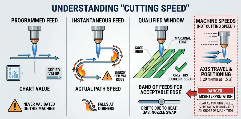
Only the third decides whether a part is scrap.
There is a fourth figure that is not a speed at all: our model sheets list a maximum running speed of 120 m/min at 1.5 G acceleration. That is axis travel and positioning, not the feed at which the beam cuts plate — read as a cutting speed it overstates throughput by an order of magnitude.
Why cutting speed alone fails without complete laser parameters
One published table can be checked line by line, and its value is not the speed row but the six rows beneath it. In a 2009 LAMP conference paper, Paul Hilton’s team at TWI cut AISI 304 stainless on a 5 kW CO2 flatbed with nitrogen using these pre-programmed recipes:
| Material thickness, mm | 0.6 | 1.2 | 3 | 6 |
|---|---|---|---|---|
| Cutting speed, m/min | 10.6 | 8 | 4.2 | 2.7 |
| Nozzle diameter, mm | 1.7 | 1.4 | 1.4 | 2.3 |
| Focus position, mm | +4.7 | +4.7 | +2.2 | −2.3 |
| N₂ pressure, bar | 12 | 12 | 17 | 16 |
| Beam diameter at lens, mm | 24 | 24 | 20 | 16 |
| Stand-off, mm | 0.7 | 0.7 | 0.7 | 0.7 |
| Focal length, mm | 250 | 250 | 250 | 250 |

Six conditions, one speed. Set that beside any chart that hands you a single cell.
Even “3 mm” is a range. ASTM A480/A480M places flat-rolled stainless dimensional tolerances in Annex A2 or A3 and lets a stricter purchase order take precedence, so a window set on one heat can sit differently on the next delivery.
Nor does speed only run out on thick plate. Hilton notes that on the two thinnest materials the disc laser’s speed “could probably have been higher but was limited by the speeds available on the cutting table used” — the motion system capped it, not the source. That is the same mechanism by which a 12 kW and a 3 kW machine converge on thin, feature-dense work. And a thickness change is never one field: a 2026 Sheet Metal Industries report on Gresham Office Furniture’s BLM installation describes automatic nozzle selection when switching thicknesses plus beam-and-parameter adaptation to hold a burr-free finish. One factory’s equipment description, not a benchmark — but nozzle, gas and beam settings travel with thickness, and a speed value does not carry them.
Why material cutting parameters cannot be scaled across metals
A mild steel/oxygen figure cannot be divided by a factor to obtain a stainless/nitrogen figure. The energy source changes, not just the number.
| Material / gas | Where the energy comes from | What caps the feed |
|---|---|---|
| Carbon steel, O₂ | beam plus an exothermic iron-oxygen reaction | oxidation, taper, spatter |
| Stainless, N₂ | beam alone; nitrogen ejects the melt | gas plant capacity, pressure stability |
| Aluminium, N₂ | beam against conductivity and reflectivity | back reflection, dross |
| Brass, copper | beam, highest reflection risk | reflected energy reaching the optics |

Hilton chose inert gas deliberately, “so as to not involve the additional exothermic energy available from the oxygen and its effects on the cut quality”. With oxygen the reaction supplies heat the beam did not. Remove it and every number moves.
For brass and copper: use a source and head approved for reflective material; confirm rated thickness and power range in writing; use the recommended gas; start conservative on controlled coupons; watch the head and optics. Never carry a carbon steel recipe across. A family overview may list copper while the model sheet stops at brass and titanium — the overview is a summary, not a specification. At high power and pressure, get written confirmation on back-reflection protection before any trial; radiation, fumes and interlocks (ISO 11553-1) belong with your safety officer, and no compliance is asserted for any installation.
How to troubleshoot laser cutting defects before changing feed rate
Most bad cuts are not a speed problem, and reaching for the feed first is how one variable becomes three. Work down this table instead — it runs in the order that costs least.
| Symptom | Check first, change nothing | Then change | How far |
|---|---|---|---|
| Will not cut through | laser output, nozzle condition, gas supply, actual sheet thickness | feed, downward | small steps, one coupon each |
| Heavy dross, bottom edge | penetration: full or partial? | gas pressure, nozzle, focus — before feed | one field at a time |
| Rough or burned top edge | optics, protective lens, gas purity | feed and power together | only once optics are clean |
| Quality drifts mid-shift | lens, nozzle wear, head temperature, gas pressure, sheet flatness | nothing yet | log the drift, then re-run |

Two cases need more than a table.
Dross tells you which way to move, if you read its shape. If the cut is fully penetrated and metal is still attached underneath, you are not short of speed — you are short of gas, or the focus is wrong, or the nozzle is worn. Lowering the feed adds heat, widens the kerf and can make it worse, because a wider kerf is harder for the jet to clear. If instead you see drag lines and a partly separated bottom, the feed is too high. Same symptom, opposite correction; the difference is penetration, not the dross.
Quality that drifts during a shift is almost never the recipe. If the first parts are good and later ones grow burrs, check lens contamination, nozzle wear, head temperature, gas supply fluctuation and sheet flatness before touching a parameter. Re-tuning the recipe to compensate for a dirty lens just moves the problem into the next shift.
7. Where the programmed feed is never reached

The feed field is a ceiling for a straight, steady cut. On a real nest the head accelerates out of a pierce, decelerates into a corner, slows around a small hole, hesitates at a microtab and follows height-sensing corrections. Energy per millimetre rises in each of those segments with no edit to the feed field.
So do not divide contour length by the chart speed. Add the segments: each run at the speed it actually holds, plus acceleration and deceleration, plus pierce, plus lead-in. Written out, T = Σ(Lᵢ/vᵢ) + Σt_accel + t_pierce + t_lead-in, where vᵢ at a corner is far below the programmed feed.
Fill that in with your own timestamps and a pattern appears: a higher straight-line feed only shortens the long steady terms, so on a nest dominated by holes and corners it barely moves cycle time. Four things decide the rest.
- Acceleration. Long straights approach the programmed maximum; small circles and sharp corners never do.
- Path and nesting. Direction changes, small features and repeated piercing add time no feed value controls.
- Piercing. Thick plate needs longer, staged pierces; on many small parts, pierce time can dominate.
- Loading and unloading. On volume work, table downtime can cancel every gain the head makes — an argument for an exchange table, not a faster feed.
These rules live in the program, so software and control support owns versions, corner rules and recipe backups, and CNC control system configuration is where you confirm which rules your controller actually exposes. A corner-rule edit changes effective speed without touching the feed field — log it as a speed change.
8. When the window has to be re-run
| Trigger | Re-run scope | Record |
|---|---|---|
| New heat, grade, coating or supplier | full ladder | mill certificate, measured thickness |
| Gas type, purity, pressure or supply mode | full ladder at that thickness | certificate, pressure at the head |
| Nozzle, orifice, centring or window changed | confirm at the band edges | component ID, before/after coupon |
| Focus zero re-calibrated after head service | full ladder | calibration date, sign convention |
| Controller, software or corner rule edited | confirm on representative geometry | program version, diff |
| Drift mid-shift with no logged change | check machine state first | cylinder change, ambient, spatter |

The last row matters most. A drift with no logged change is a machine signal, not a recipe signal. In the same 2021 FABRICATOR feature, Tigmaster’s clock-in data showed fifty minutes spent on a job that should have taken under ten, with the hours going into finding material rather than cutting; as Tim Heston puts it, “a shop’s overall cutting capacity isn’t measured by the speed of the cutting head.”
Nozzles, protective windows and ceramic rings are the consumables that quietly move gas flow and delivered energy; planned maintenance and calibration covers optical path alignment and re-establishing focus zero. A re-run after either costs a shift. Three shifts of rework costs more.9. Choosing the machine, and what to settle in writing
Because the window depends on grade, thickness, gas and geometry, machine choice is a process decision before it is a specification comparison.
| Selection factor | What it decides |
|---|---|
| Laser power | the thickest job you can hold a stable band on |
| Cutting head | focal configuration and nozzle compatibility, not just wattage |
| Gas system | whether pressure at the head holds through a full sheet |
| Motion system | achievable speed on small features and corners |
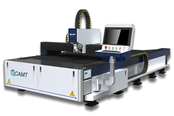
At CAMT (Nanjing Huameng Machinery Technology) three platforms frame this: the open-type ULF single-table cutter at 1–6 kW for mixed sheet at moderate volume; the enclosed ULE with twin exchange tables at 6–12 kW, Raytools auto-focus head and CypCut control, for volume work with one table cutting while the other loads; and the ULT plate-and-tube machine at 1–6 kW for profiles alongside sheet.
All publish running speed and acceleration as motion ratings — the fiber laser cutting machine range is the family overview, not the specification. Use the model sheet and its revision date.
Three things to get in writing at trial:
- which recipes ship, for which grade, thickness, gas, nozzle and controller version;
- whether a quoted speed is programmed feed, straight-line measurement or nest cycle time, and the conditions behind it;
- who re-runs the window and re-establishes focus zero after head service, and whether the library can be versioned and restored.
Run the trial on your own stock: one nest carrying the daily thickness, the thickest job you accept, a small hole and a sharp corner, signed against the coupon set rather than a brochure number. Operator and maintenance training covers feed, power curves, focus, gas and nozzle centring; remote diagnostics and technical support reconstructs a drift from serial, error logs and parameter history — scope, not performance.
We will not claim that a machine removes the need for trial cuts, that a factory recipe survives a new gas supplier or heat, or that any figure here was measured on your material. What we can put in writing is which recipes ship, what the retained coupon must demonstrate, and who re-establishes focus zero. Send your grade, thickness band, gas and coupon record and we will build the trial around the criterion your process needs.